Punching fixture for refrigerator lower beam

A refrigerator and punching technology, applied in the direction of piercing tools, manufacturing tools, metal processing equipment, etc., can solve problems such as easy cracks

Active Publication Date: 2017-02-22
重庆科泰表面处理有限公司
View PDF5 Cites 3 Cited by
  • Summary
  • Abstract
  • Description
  • Claims
  • Application Information

AI Technical Summary

Problems solved by technology

[0004] The present invention intends to provide a punching tool for the lower beam of a refrigerator to solve the problem of cracks in the prior art when punching the L-shaped lower beam of the refrigerator

Method used


Image

  • Punching fixture for refrigerator lower beam
  • Punching fixture for refrigerator lower beam
  • Punching fixture for refrigerator lower beam

Examples


Embodiment 1

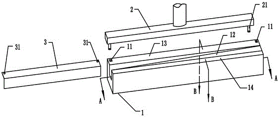
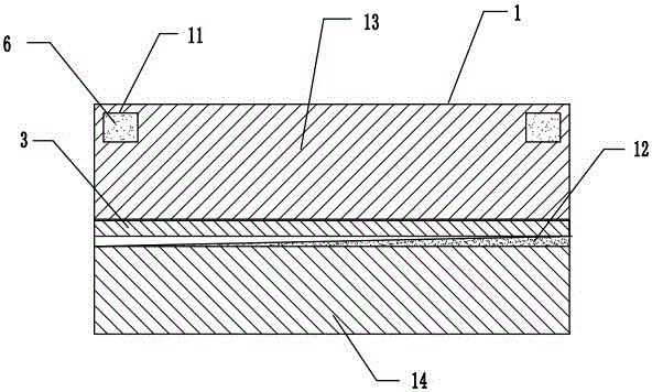
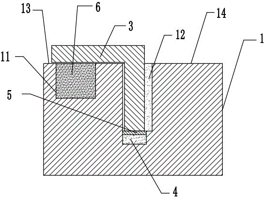
[0023] The reference signs in the accompanying drawings of the description include: punch mechanism 1, punch mechanism 2, L-shaped lower beam 3, air bag 4, rubber strip 5, ice cube 6, rectangular groove 11, elastic strip 12, punch table top 13, wedge-shaped abutment Block 14, punch 21, door reamer 31.

[0024] Such as figure 1 As shown: the punch mechanism 1 includes a punch table 13 and a wedge-shaped block 14 that stand opposite each other. A channel that can be inserted into the L-shaped lower beam 3 is formed between the punch table 13 and the wedge-shaped block 14. One end of the channel is narrow and the other end is wide, and the end of the channel is wide. The L-shaped lower beam 3 is inserted, and a rectangular groove 11 is arranged at both ends of the punch table 13, and the rectangular groove 11 is filled with ice cubes 6, and the wedge-shaped surface of the wedge-shaped block 14 is provided with a rubber elastic strip 12, and the punch press A stamping mechanism 2...

Embodiment 2

[0029] The difference from Embodiment 1 is that the ice cubes 6 in the grooves are replaced with ice water flush with the punch table 13, and then the ice water is frozen into ice cubes 6. Utilize the groove to be full of ice water and freeze into ice cube 6 again, such ice cube 6 has reduced the error between the ice cube 6 plane and the punch table 13, has guaranteed the supporting effect of ice cube 6 to L-shaped lower beam 3, prevents ice The gap between the block 6 and the punch table 13 causes non-horizontal deformation of the door hinge hole 31 after punching.

[0030] The beneficial effects of the present invention are: 1. The L-shaped lower beam is covered on the ice cube, and the ice cube can support the L-shaped lower beam. The lower beam is broken; 2. When stamping, the right-angle inner corner of the L-shaped lower beam is stuck on the right-angled edge of the punch table, and the narrower side between the wedge-shaped block and the punch table fixes the L-shaped ...


PUM


Abstract

The invention relates to the technical field of the manufacturing of refrigerator lower beam, and particularly relates to a punching fixture for refrigerator lower beam. The fixture comprises a punching mechanism and a stamping mechanism located below the punching mechanism. The punching mechanism comprises a wedge block and a punching table facing the wedge surface of the wedge block. An elastic strip is placed on the wedge surface of the wedge block. Both sides of the punching table are provided with rectangular grooves, wherein ice blocks are placed in the rectangular grooves. A punching head matching the rectangular grooves is placed on the stamping mechanism. The ice blocks are used to support the L shape lower beam, and to transfer the residual strength on the punching head to prevent the breaking of the L shape lower beam during the stamping operation in the thin and narrow side edges. The elastic strip positioned on the wedge block can simultaneously clamp the L shape lower beam and exert a function of relieving pressure to the side board of the L shape lower beam, and prevent the side board of the L shape lower beam from breaking in the stamping process.

Description

technical field [0001] The invention relates to the field of manufacturing equipment for refrigerator lower beams, in particular to a punching tool for refrigerator lower beams. Background technique [0002] The box body of the refrigerator includes an outer shell, an inner tank, a front top plate, a middle beam and a lower beam, wherein the front top plate, the middle beam and the lower beam are all metal sheet parts, and the overall shape of the lower beam is an angle steel shape bent by a steel plate at a right angle, namely L-shaped lower beam, the lower beam is arranged at the lower part of the front of the box body, the lower beam made of metal enables the magnetic door seal to be sucked and sealed, and the lower beam is provided with a hole for door hinge installation. [0003] In the prior art, the door reaming hole on the lower beam is mainly processed by stamping. When stamping, the punch is directly pressed down on the workpiece on the punching machine, and punchi...

Claims


Application Information

Patent Timeline
IPC IPC(8): B21D28/34B21D53/00
CPCB21D28/34B21D53/00
Inventor 王元清
Owner 重庆科泰表面处理有限公司
Why Eureka
Try Eureka