High precision tool adjusting mechanism for lathe

A tool adjustment, high-precision technology, applied in the direction of tool holders, manufacturing tools, metal processing machinery parts, etc., can solve the problems of limited adjustment accuracy, instability, complex structure, etc., to achieve good machining accuracy, low manufacturing cost, not easy damage effect

Active Publication Date: 2017-02-22
江苏瑞尔隆盛叶轮科技有限公司
View PDF6 Cites 3 Cited by
  • Summary
  • Abstract
  • Description
  • Claims
  • Application Information

AI Technical Summary

Problems solved by technology

[0004] 1) Poor rigidity: When there is heavy cutting, or when the cutting force has a sudden change, the position of the tool seat will change slightly, and the ideal accuracy cannot be guaranteed;
[0005] 2) Instability: In long-term batch processing, the position of the tool seat cannot be guaranteed for a long time; the position of the tool needs to be checked regularly;
[0006] 3) The production of the knife seat is difficult: relying on structural positioning such as dovetail grooves, the requirements for machining accuracy and assembly accuracy are high, and the structure is complex;
[0007] 4) Difficulty in adjusting the technology: it is necessary to repeatedly scrutinize the size of the screw before and after locking and the locking force. Generally, it takes 30 minutes to adjust a knife seat;
[0008] 5) The adjustment accuracy is limited: due to the insufficiency caused by the design and structure of the tool holder itself, it is difficult to compensate for the artificial adjustment in the later stage, and the space adjustment angle of the tool holder is limited;
[0009] 6) Easy to be damaged: Due to the limitation of equipment specification stroke, some adjustment structure design is relatively thin, and the screw specification is below M5, which is easy to slip and damage

Method used


Image

  • High precision tool adjusting mechanism for lathe
  • High precision tool adjusting mechanism for lathe
  • High precision tool adjusting mechanism for lathe

Examples


Embodiment Construction

[0034] Preferred embodiments of the present invention will be described in detail below in conjunction with the accompanying drawings.

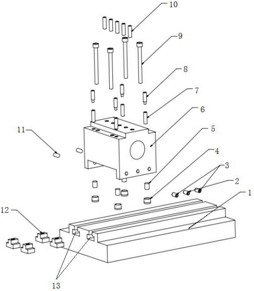
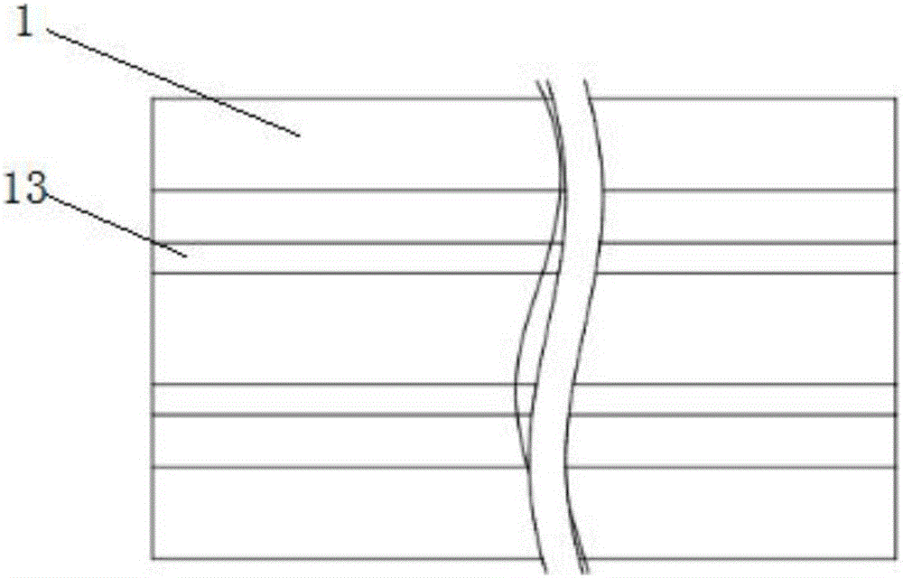
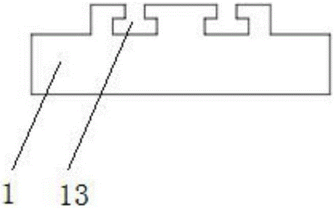
[0035] see Figure 1 to Figure 3 , the invention discloses a high-precision tool adjustment mechanism for a lathe, which includes a base plate 1 and a tool seat 6 arranged on the base plate. Two stepped grooves 13 are arranged in parallel on the base plate 1, and the stepped grooves 13 are slidingly embedded Several step nuts 12 are provided, and several sets of locking screw holes 91 and locking screws 9 that cooperate with each other are provided on the knife seat 6, and the locking screw holes 91 and locking screws 9 are arranged corresponding to the aforementioned step grooves 13. , the bottom plate 1 and the knife seat 6 are locked by locking screws 9 and stepped nuts 12 . The above-mentioned step groove 13 and the step nut 12 inside can move the locking position, which facilitates the adjustment of the position of the tool holder 6 . ...


PUM


Abstract

The invention discloses a high precision tool adjusting mechanism for a lathe. The high precision tool adjusting mechanism for the lathe comprises a bottom plate and a tool base arranged on the bottom plate; the bottom plate is provided with two step grooves in parallel, and a plurality of step nuts are embedded in the step grooves in a sliding manner; the tool base is provided with a plurality of locking screw holes and locking screws, and the locking screw holes and the locking screws are matched with each other; the locking screw holes and the locking screws correspond to the above-mentioned step grooves; and the bottom plate and the tool base are locked through the locking screws and the step nuts. According to the high precision tool adjusting mechanism for the lathe, under the condition that the heavy cutting force is borne or the cutting force is suddenly changed, ideal precision can still be guaranteed. The high precision tool adjusting mechanism for the lathe is elaborate in design and convenient to assemble, and good machining precision can be achieved; and the purposes of achieving the positioning precision within 3 microns and achieving full-angle and high-precision adjustment on the space where the tool base is located can be achieved within a short time, and the high precision tool adjusting mechanism for the lathe is low in manufacturing cost, long in service life, not prone to damage, good in rigidity and capable of being applicable to long time and large batch production operation.

Description

technical field [0001] The invention belongs to the field of machining technology and relates to a lathe, in particular to a high-precision tool adjustment mechanism for a lathe. Background technique [0002] With the development of today's industry, the design of mechanical parts is becoming more and more strict tolerance requirements, and the development of CNC equipment is also tending to pursue high progress, high efficiency and good processing stability. According to the ISO standard, the positioning accuracy of the current high-precision CNC lathe has reached within 5 μm, and the repeat positioning accuracy is within 3 μm; If the coaxial error with the spindle axis is controlled within a small range, it will be difficult to make high-precision parts no matter how high the precision of the lathe is. [0003] At present, among the global lathe manufacturers, many manufacturers do not have adjustable tool clamping mechanisms. Some Japanese manufacturers have tool seats t...

Claims


Application Information

Patent Timeline
Patent Type & Authority Applications(China)
IPC IPC(8): B23B29/04B23Q3/00
CPCB23B29/04B23Q3/00
Inventor 韩海龙
Owner 江苏瑞尔隆盛叶轮科技有限公司
Why Eureka
Try Eureka