Automatic receiving and transferring device for pneumatic material conveying system

A pneumatic conveying, automatic sending and receiving technology, applied in the direction of conveyor, transportation and packaging, etc., can solve the problems that affect the efficiency of sampling and preparation, high use cost, shedding, etc., to ensure high-speed transmission efficiency, continuous operation, deceleration and buffering effect of effect

Active Publication Date: 2017-02-22
HUNAN SUNDY SCI & TECH DEV
View PDF10 Cites 11 Cited by
  • Summary
  • Abstract
  • Description
  • Claims
  • Application Information

AI Technical Summary

Problems solved by technology

Firstly, this method requires a high degree of matching between the pipe and the sample bottle. The staff needs to design the sample bottle according to the size of the pipe, or design the pipe according to the size of the sample bottle. very inconvenient
The second is that this method does not protect the sample bottle, and the air pressure directly acts on the sample bottle, which may easily cause serious consequences such as sample bottle rupture or even sample bottle explosion.
At the same time, the sample bottle is easy to collide with the pipeline during the high-speed transmission process, resulting in damage to the sample bottle and sample leakage
The third is that the sample bottle directly rubs against the pipeline. During high-speed transmissi

Method used


Image

  • Automatic receiving and transferring device for pneumatic material conveying system
  • Automatic receiving and transferring device for pneumatic material conveying system
  • Automatic receiving and transferring device for pneumatic material conveying system

Examples


Embodiment Construction

[0039] The present invention will be described in further detail below in conjunction with specific embodiments and accompanying drawings.

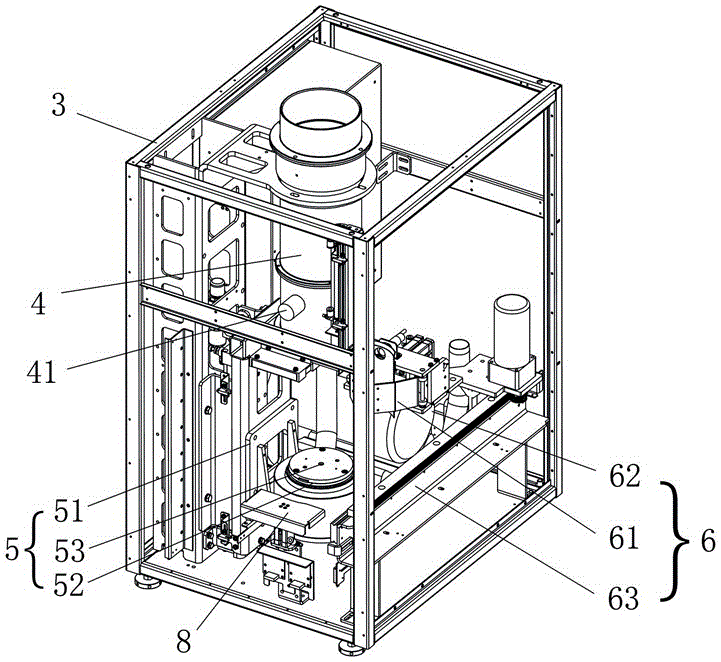
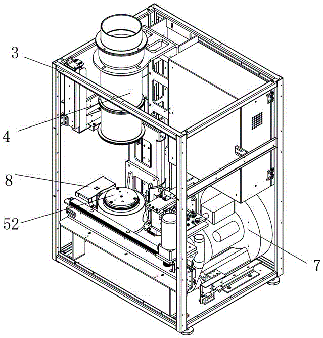
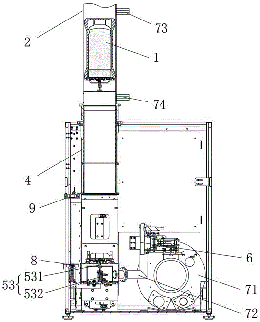
[0040] Such as Figure 1 to Figure 6 As shown, the present invention provides an automatic sending and receiving device for a material pneumatic conveying system, which is connected to a pneumatic conveying pipeline unit 2 for conveying objects 1, and includes a cabinet 3, which is provided with a sending and receiving pipeline 4, a support The sample lifting platform unit 5 and the manipulator unit 6, the upper end of the sending and receiving pipeline 4 is used to communicate with the pneumatic transmission pipeline unit 2; The conveyed object 1 is lifted up and sent into the sending and receiving pipeline 4 for pneumatic conveying, or after receiving the conveying object 1 transmitted by the sending and receiving pipeline 4, it falls downward; The transported object 1 is picked and placed from the outside of the cabinet 3 onto the sam...


PUM


Abstract

The invention discloses an automatic receiving and transferring device for a pneumatic material conveying system. The automatic receiving and transferring device is connected to a pneumatic conveying pipeline unit used for conveying objects to be conveyed and comprises a cabinet body, and a receiving and transferring pipeline, a supporting and lifting platform unit and a manipulator unit are arranged inside the cabinet body; the upper end of the receiving and transferring pipeline is used for communicating with the pneumatic conveying pipeline unit; the supporting and lifting platform unit is matched with the receiving and transferring pipeline, does lifting motion below the receiving and transferring pipeline and is used for lifting the objects to be conveyed upwards, conveying the objects to be conveyed into the receiving and transferring pipeline for pneumatic conveyance and used for falling down after receiving the objects to be conveyed from the receiving and transferring pipeline; and the manipulator unit is arranged on one side of the lifting platform unit and is used for placing the objects to be conveyed from the exterior of the cabinet body on the lifting platform unit for lifting the objects and conveying the objects pneumatically and used for placing the objects to be conveyed on the lifting platform unit outside the cabinet body. The automatic receiving and transferring device has the advantages that the structure is simple and compact and the automation degree is high.

Description

technical field [0001] The invention mainly relates to the field of equipment for collecting and processing material samples, and in particular to an automatic sending and receiving device for a material pneumatic conveying system. Background technique [0002] For the sampling, sample preparation, and testing of material (such as ore, coal) samples, each country has mandatory standards, and the sampling and processing of samples must be carried out in accordance with the standards. The principle of sample sampling, sample preparation, and testing work process is to gradually reduce the particle size and quality of the collected samples without destroying the representativeness of the sample, until it meets the particle size and quality of the sample in the laboratory test ( Weight) accuracy requirements, and then carry out relevant laboratory analysis on the samples that meet the requirements. For example, taking coal sampling as an example, it is actually a sampling and a...

Claims


Application Information

Patent Timeline
IPC IPC(8): B65G51/02B65G51/12B65G51/36
CPCB65G51/02B65G51/12B65G51/36
Inventor 任率
Owner HUNAN SUNDY SCI & TECH DEV
Why Eureka
Try Eureka