Efficient energy-saving stable type steel slag pyrolyzer

A high-efficiency energy-saving, cracking furnace technology, applied in the direction of improving energy efficiency, furnace, furnace charge, etc., can solve the problems of unsatisfactory treatment effect, simple structure, etc., and achieve the effects of efficient recovery, improved production efficiency, and extended life

Active Publication Date: 2017-02-22
SHAOGUAN QUJIANG SHENGDA EQUIP & MATERIALS
View PDF6 Cites 3 Cited by
  • Summary
  • Abstract
  • Description
  • Claims
  • Application Information

AI Technical Summary

Problems solved by technology

[0006] The purpose of the present invention is to provide a high-efficiency, energy-saving and stable steel slag cracking furnace for the problem that the structure of the existing steel slag cracking furnace is too simple, and the treatment effect is not ideal when processing hot steel slag.

Method used


Image

  • Efficient energy-saving stable type steel slag pyrolyzer
  • Efficient energy-saving stable type steel slag pyrolyzer
  • Efficient energy-saving stable type steel slag pyrolyzer

Examples


Embodiment 1

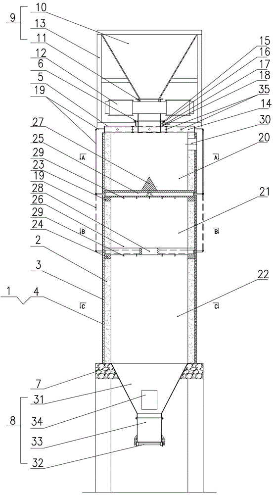
[0047] In this embodiment, 200m 3 , a steel slag cracking furnace with a daily processing capacity of 900 tons / furnace is taken as an example to explain the technical solution of the present invention in detail, but this embodiment does not limit the present invention in any form.

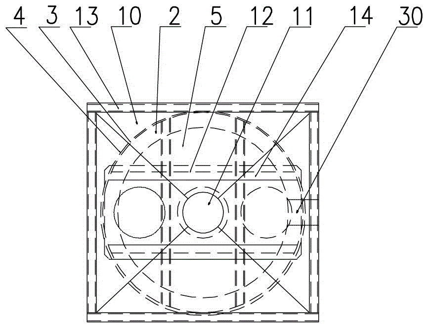
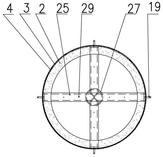
[0048] see Figure 1~5 , the technical scheme of the present invention is: a kind of high-efficiency energy-saving stable steel slag cracking furnace, has furnace body 1, and furnace body 1 is provided with working lining 2, heat insulation layer 3 and furnace shell 4 successively from inside to outside, and the top of furnace body 1 A furnace cover 5 is installed, and the center of the furnace cover 5 is provided with a feed pipe 6, and the bottom of the furnace body 1 is provided with a furnace body support platform 7, and a furnace bottom discharge device 8 is installed below the furnace body support platform 7, especially:

[0049] A. A furnace top charging device 9 is also installed above the...


PUM

PropertyMeasurementUnit
heightaaaaaaaaaa
diameteraaaaaaaaaa
heightaaaaaaaaaa

Abstract

The invention relates to the technical field of comprehensive utilization of steel slag, in particular to an efficient energy-saving stable type steel slag pyrolyzer. The pyrolyzer is provided with a pyrolyzer body, a water-cooling pyrolyzer cover is arranged at the top of the pyrolyzer body, a feeding pipe is arranged in the center of the pyrolyzer cover, a pyrolyzer top charging device is arranged above the pyrolyzer cover, and a discharging device is arranged at the bottom of the pyrolyzer body; a vapor bath-cooling belt, a spray fast-cooling belt and a tank-type hot disintegrating belt are sequentially arranged in the pyrolyzer body from top to bottom, the working linings corresponding to the vapor bath-cooling belt, the mist spray fast-cooling belt and the tank-type hot disintegrating belt are each separated by an upper joist ring and a lower joist ring, an upper cross type bearing beam and a lower cross type bearing beam are arranged above the corresponding upper joist ring and the corresponding lower joist ring respectively, the inner of each cross type bearing beam is of a hollow communication structure, an atomization nozzle is arranged on the bottom face of each cross type bearing beam, and the end heads of the upper cross type bearing beam and the lower cross type bearing beam are in butt joint with water outlet pipes of the water-cooling pyrolyzer cover respectively. The pyrolyzer is clever in design and good in tank-type hot disintegrating effect, and can achieve automation control of the whole process from dumping the molten steel slag into the pyrolyzer to discharging the molten steel slag out and stable transformation and utilization of the sensible heat of the molten steel slag, and is a revolutionary improvement to steel slag processing devices.

Description

technical field [0001] The invention relates to the technical field of steel slag comprehensive utilization, in particular to a high-efficiency, energy-saving and stable steel slag cracking furnace. Background technique [0002] my country's crude steel output has exceeded 800 million tons per year, and about 120kg of steel slag will be produced for every ton of crude steel produced. It is wrapped with about 10% metallic iron, and the sensible heat of each ton of hot steel slag is not less than the calorific value of 60kg of standard coal. The annual production of 800 million tons of crude steel means that about 100 million tons of steel slag are produced, of which about 10 million Tons / year of metal iron needs to be recycled, and the sensible heat of steel slag equivalent to 6 million tons / year of standard coal needs to be recycled. [0003] At present, the treatment methods of hot steel slag in my country mainly include hot stewing method (steam pot method), hot pouring met...

Claims


Application Information

Patent Timeline
Patent Type & Authority Applications(China)
IPC IPC(8): C21B3/06F27D17/00
CPCC21B3/06F27D17/004F27M2001/10F27M2003/14Y02P10/25Y02W30/50
Inventor 何福礼郭建郭心岭
Owner SHAOGUAN QUJIANG SHENGDA EQUIP & MATERIALS
Why Eureka
Try Eureka