
Automatic feeding and edge-aligning machine for sewing material, method and sewing machine

A technology for automatic material feeding and sewing machines, which is applied to sewing machine components, sewing machine control devices, cloth feeding mechanisms, etc. even material effect

Active Publication Date: 2017-02-22
廖晓阳
View PDF5 Cites 4 Cited by
  • Summary
  • Abstract
  • Description
  • Claims
  • Application Information

AI Technical Summary

Problems solved by technology

In the production process of the sofa, it is also necessary to carry out sewing and sewing pattern operations on the sewing material. In the existing operation, the sewing material is placed on the drum, and workers are required to guard the drum all the time. Unloading, time-consuming and labor-intensive
In addition, the sewing patterns on the sofa sewing materials are different, which will lead to different changes in the left and right swing ranges of the sewing machine. At this time, the position of the sewing materials on the drum should also be adjusted adaptively with the change of the sewing machine position. It needs to be realized through manual adjustment, which greatly increases the labor cost

Method used


Image

  • Automatic feeding and edge-aligning machine for sewing material, method and sewing machine
  • Automatic feeding and edge-aligning machine for sewing material, method and sewing machine

Examples


Embodiment 1

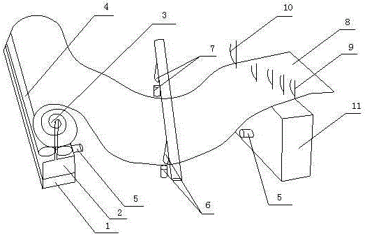
[0023] The present invention includes an automatic feeding and edge-aligning machine for sewing materials, comprising a tubular material 3, a sewing material 8 positioned on the tubular material 3, and a sewing machine base 11, and the tubular material 3 is located on one side of the sewing machine base 11 and is parallel Arrangement, characterized in that it also includes a horizontal chute seat 1, a base 2 and a plurality of push rollers 4 located at the bottom of the cylindrical material 3 and capable of pushing the cylindrical material 3 to move and discharge in the longitudinal direction, and the base 2 is installed on the horizontal chute seat 1 and can slide horizontally, the two ends of the tubular material 3 and a plurality of push rollers 4 are installed on the base 2; on the opposite surfaces of the base 2 and the sewing machine base 11, an infrared through-beam sensor A5 is respectively installed, and two The infrared through-beam sensors A5 are opposite; a pair of ...

Embodiment 2

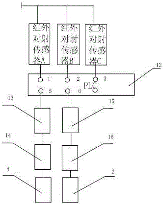
[0027] Such as figure 2 As shown, the present embodiment is preferably as follows on the basis of embodiment 1: the signals of two infrared through-shooting sensors A5 are imported into the sampling input port 1 of PLC programmable logic controller 12, and the signals of a pair of infrared through-shooting sensors B6 are transmitted into the sampling input port 2 of the PLC programmable logic controller 12, the signal of a pair of infrared radiation sensors C7 is introduced into the sampling input port 3 of the PLC programmable logic controller 12, and the output port 5 of the programmable logic controller 12 is connected in turn The solenoid valve 13 , the driving motor A14 and the push roller 4 , and the output port 6 of the programmable logic controller 12 are connected to the relay 15 , the driving motor B16 and the base 2 in sequence. This method is an implementation method. The signals of multiple pairs of infrared cross-radiation sensors are collected by the programmab...

Embodiment 3

[0030] A method for automatically feeding and aligning edges for sewing materials, comprising the steps of:

[0031] a) Use two infrared cross-beam sensors A to conduct cross-fire between the base and the sewing machine base, and detect the length of the tubular material in real time; use a pair of infrared cross-beam sensors B and a pair of infrared cross-beam sensors C respectively Carry out vertical shooting on both sides of the sewing material, and detect in real time whether the sewing material is shifted to the left or right when the roller is put down;

[0032] b) When the infrared pulse beam between the two infrared facing sensors A is blocked, the signal will be transmitted to the sampling input port 1 of the programmable logic controller and trigger the disconnection of the solenoid valve to stop the drive motor A, Avoid pushing the roller to push the tubular material down to the sewing material;

[0033] c) When the infrared pulse beam between a pair of infrared se...


PUM


Abstract

The invention discloses an automatic feeding and edge-aligning machine for a sewing material, a method and a sewing machine. The automatic feeding and edge-aligning machine for the sewing material comprises a cylindrical material, the sewing material and a sewing machine base, and also comprises a transverse sliding groove base, a pedestal and a plurality of pushing rollers, wherein the sewing material is positioned on the cylindrical material; the pushing rollers are positioned at the bottom of the cylindrical material and can push the cylindrical material to longitudinally move to be fed; the pedestal is mounted on the transverse sliding groove base and can slide transversely; the two ends of the cylindrical material and the two ends of the pushing rollers are mounted on the pedestal; an infrared opposite-emission sensor is mounted on each of the opposite surfaces of the pedestal and the sewing machine base. A detection method is as follows: the two infrared opposite-emission sensors A perform opposite-emission between the pedestal and the sewing machine base to realize automatic feeding of the sewing material; a pair of infrared opposite-emission sensors B and a pair of infrared opposite-emission sensors C perform opposite-emission in the vertical directions of the two sides of the sewing material correspondingly to realize edge-aligning operation of the sewing material. According to the automatic feeding and edge-aligning machine for the sewing material, the method and the sewing machine, automatic feeding operation of the sewing material and automatic edge-aligning operation of the sewing material are realized, and the labor cost is greatly reduced.

Description

technical field [0001] The invention relates to the field of sewing, in particular to an automatic feeding and matching machine for sewing materials, a method and a sewing machine. Background technique [0002] Sewing refers to the operation of using one or more sewing threads to form one or more stitches on the sewing material to interweave or sew one or more layers of sewing materials, generally using a sewing machine. The sewing machine generally includes four parts: the machine head, the machine base, the transmission and the accessories. The machine head is the main part of the sewing machine. Composition, the movement of each mechanism is reasonably coordinated, and the cycle works to sew the sewing materials together. The machine base is divided into two forms: table and chassis. The table of the table-type machine base plays the role of supporting the machine head. The transmission part is composed of a frame, a hand crank or a motor and other components. [0003] ...

Claims


Application Information

Patent Timeline
Patent Type & Authority Applications(China)
IPC IPC(8): D05B35/00D05B69/00
CPCD05B35/00D05B69/00
Inventor 廖晓阳
Owner 廖晓阳
Learn More