
Combined groove-type ironing machine

An ironing machine and hybrid technology, applied in the field of ironing machines, can solve the problems of rolling, linen wrinkling, etc., and achieve the effects of good ironing quality, optimized design and excellent wrapping.

Active Publication Date: 2017-02-22
江苏威士智能装备有限公司
View PDF8 Cites 6 Cited by
  • Summary
  • Abstract
  • Description
  • Claims
  • Application Information

AI Technical Summary

Problems solved by technology

[0006] At present, domestic laundry factories generally use steam as the heat source of the ironing machine. The steam usually comes from power plants, coal boilers, oil-fired boilers and gas boilers. Many manufacturers cannot guarantee that the ironing machine has a stable gas above 0.6MPa due to gas source problems or installed capacity problems. Source supply, when wet linen enters the first trough, a large amount of water will be taken away, and the temperature of the trough will drop rapidly. If the timely replenishment of heat cannot be guaranteed, the linen will be wrinkled and rolled when the temperature is lower than a certain value.

Method used


Image

  • Combined groove-type ironing machine
  • Combined groove-type ironing machine
  • Combined groove-type ironing machine

Examples


Embodiment 1

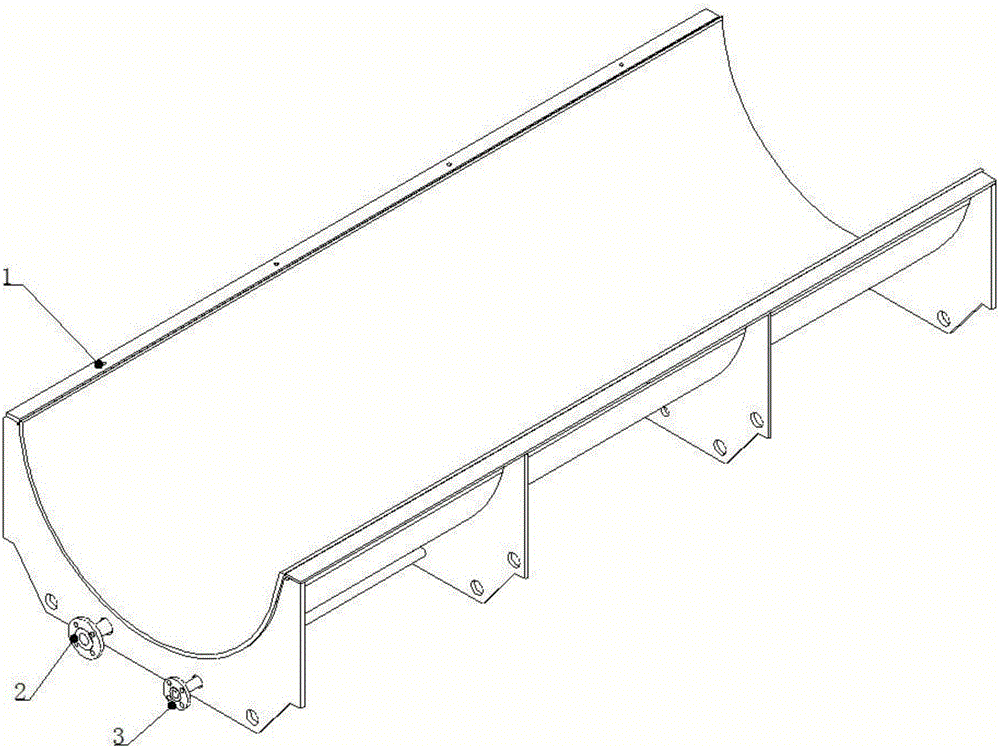
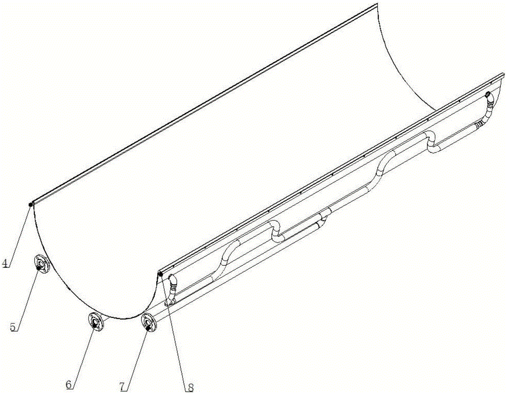
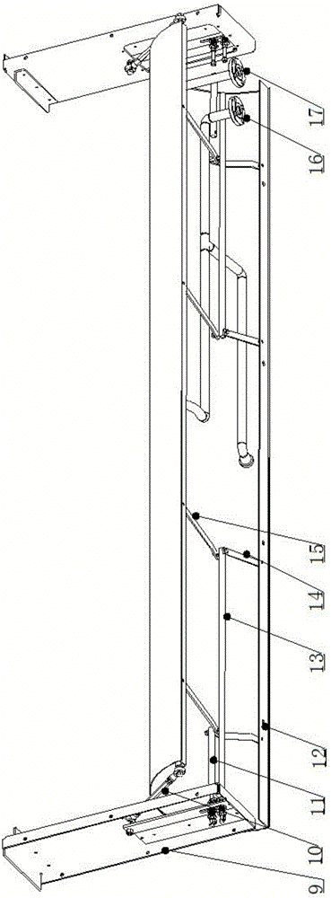
[0030] see Figure 1-Figure 5 , a hybrid trough-type ironing machine, the biggest difference from common trough-type ironing machines is that it combines the characteristics of rigid trough and flexible trough, and the rigid trough and flexible trough are used together, and the size of the rack installation is consistent. The accompanying drawings further illustrate:

[0031] from figure 1 You can see the steam inlet 2 and the condensed water outlet 3 of the rigid tank. The steam flows through the steam chamber of the rigid tank to transfer heat to the tank body. In this picture, the linen enters from the right end and is discharged from the left end. 4 transition slot mounting holes 1, bolts 21 can be used to image 3 The corresponding transition groove installation holes 12 are connected.

[0032] figure 2 5 and 7 in the flexible tank are the steam inlet, and 6 is the condensed water outlet. In the position shown in the figure, the left side is the discharge direction. ...


PUM


Abstract

The invention relates to a combined groove-type ironing machine. The combined groove-type ironing machine comprises an ironing groove set. Ironing grooves are in arc shapes with upward arc openings. The ironing groove set comprises at least one rigid groove and at least one flexible groove, and transition grooves with downward arc openings are arranged between the ironing grooves; the first ironing groove of the ironing groove set is a rigid groove, and the second ironing groove of the ironing groove set is a flexible groove; transition-groove installation holes used for being connected with the horizontal edge portions of the transition grooves are formed in the horizontal edge portions of the two ends of the rigid grooves; the transition grooves are fixed onto racks of the rigid grooves and the flexible grooves through installation supports on the two sides. According to the combined groove-type ironing machine, the excellent heat storage performance of the rigid grooves and the ironing effect of the flexible grooves of the ironing machine are combined, cloth grass with a large amount of moisture firstly enters the rigid grooves, and the large amount of moisture is removed; meanwhile, the problem that as supplying of steam is insufficient, the temperature of groove bodies is suddenly lowered, and halting occurs accordingly is solved, and after the damp-dry cloth grass enters the flexible grooves, the good ironing quality can be achieved through the rapid heat exchange capacity, the smooth contact faces and the excellent packaging performance of the thin plate structures of the flexible grooves.

Description

technical field [0001] The invention relates to a trough type ironing machine, which belongs to the technical field of ironing machines. Background technique [0002] The ironing machine is used for the finishing process of the laundry room. After washing and pre-drying, linen such as bed sheets and quilt covers need to be sent to the ironing machine to evaporate the residual water. During this process, the linen is heated and pressurized. become dry and flat. According to the structure, the ironing machine can be divided into two categories: groove type ironing machine and roller type ironing machine. From the name, it can be roughly understood that the groove type ironing machine is heated by the groove, while the roller type ironer is heated by the roller. [0003] The ironing tank is the core component of the tank ironing machine. Currently, there are two commonly used forms: a rigid tank welded and processed with thick steel plates and a flexible tank welded and polish...

Claims


Application Information

Patent Timeline
Patent Type & Authority Applications(China)
IPC IPC(8): D06F69/00
CPCD06F69/00
Inventor 吕立毅王国顺彭金华刘峰
Owner 江苏威士智能装备有限公司
Learn More