Transverse-direction low-yield-point energy dissipation type steel bridge anti-seismic stop block structure and arranging method

A low-yield point, energy-consuming technology, used in bridges, bridge parts, bridge construction, etc., can solve the problems of irreparable blocks, bridge beam falling beam damage, collision area damage, etc., to achieve easy detection and maintenance, prevention The effect of falling beam damage and low material price

Active Publication Date: 2017-02-22
NANCHANG UNIV
View PDF10 Cites 8 Cited by
  • Summary
  • Abstract
  • Description
  • Claims
  • Application Information

AI Technical Summary

Problems solved by technology

[0003] At present, in order to limit the relatively large displacement of the upper girder body in the transverse direction of the bridge, reinforced concrete stoppers are often installed on the top of the bridge pier cap beam, but there are relatively few studies on restricting the relatively large displacement of the upper girder body along the bridge direction
However, bridges in earthquakes often suffer from beam damage along the direction of the bridge.
The collision between the ordinary reinforced concrete block and the beam body is a rigid collision between concrete, which is easy to cause local damage to the reinforced concrete block and the bridge beam body, and the horizontal shear force of the reinforced concrete block is usually insufficient

Method used


Image

  • Transverse-direction low-yield-point energy dissipation type steel bridge anti-seismic stop block structure and arranging method
  • Transverse-direction low-yield-point energy dissipation type steel bridge anti-seismic stop block structure and arranging method
  • Transverse-direction low-yield-point energy dissipation type steel bridge anti-seismic stop block structure and arranging method

Examples


Example Embodiment

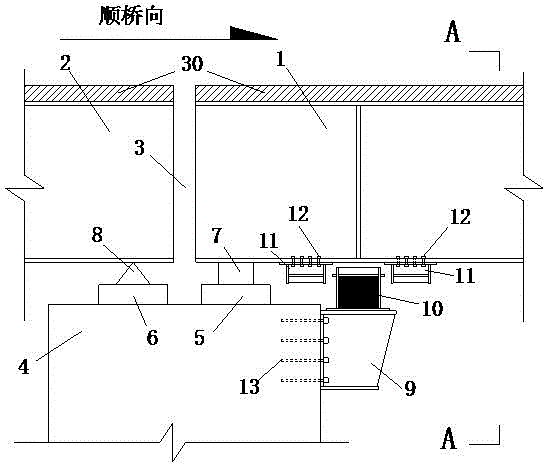
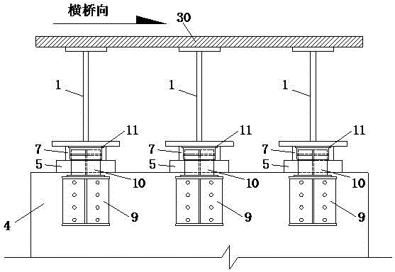
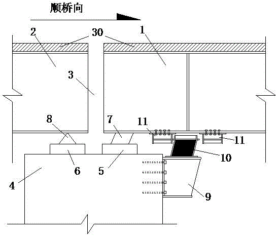
[0025] Such as Figure 1 to Figure 7 As shown, a specific embodiment of an energy-dissipating steel bridge seismic block structure and arrangement method of a low yield point along the bridge of the present invention includes a steel corbel 9, a block body 10, and a steel frame 11. The bridge type selected in this embodiment is an I-shaped steel plate composite girder bridge, and the bridge seismic block structure and arrangement method are also applicable to other bridge types such as prestressed concrete bridges and steel bridges.

[0026] Such as Figure 1 to Figure 4 As shown, the main girder 1 of the bridge and the other main girder 2 of the bridge are disconnected at the top of the pier 4 to form an expansion joint 3. Along the bridge direction at the expansion joint 3, on the top of the pier 4, a bridge support cushion stone 5 and another bridge support cushion stone 6 are set, and the movable bridge support 7 is set on the bridge support cushion stone 5, and the bridge is...


PUM


Abstract

The invention discloses a transverse-direction low-yield-point energy dissipation type steel bridge anti-seismic stop block structure and an arranging method. The bridge anti-seismic stop block structure comprises a steel corbel, a stop block body and a steel frame, wherein the steel corbel is fixed to the side face of the top of the portion, nearby a movable support, of a bridge pier, the stop block body is fixed to the steel corbel, and the steel frame is fixed to the bottom of a bridge body. The anti-seismic stop block structure is arranged nearby each movable support, the collision positions are disperse, multiple anti-seismic stop block structures are arranged, therefore, the seismic force acting on each stop block structure can be effectively decreased, and then local damage of the stop block structures can be reduced; each stop block body comprises an energy dissipation type low-yield-point steel plate. According to the bridge anti-seismic stop block structure, large displacement between beam bodies and the bridge piers can be effectively limited, and damage of the movable supports and expansion joints can be reduced; under the action of a violent seism, not only can local damage of the collision areas and damage transmitted to the bottoms of the bridge piers be effectively reduced, but also part of seismic energy can be dissipated by means of plastic deformation of the energy dissipation type low-yield-point steel plates arranged in the stop block bodies.

Description

technical field [0001] The invention belongs to the field of anti-seismic technology of bridges, and in particular relates to an anti-seismic stopper structure and arrangement method of steel energy-dissipating bridges with low yield point along the direction of the bridge. Background technique [0002] my country is located between the Pacific seismic belt and the Eurasian seismic belt, and is one of the most earthquake-prone countries in the world. The earthquakes that occur have the characteristics of high intensity, wide distribution, shallow focus and particularly severe earthquake damage. Most of the bridges built are in the hub position and throat of highway traffic, and are an important part of the lifeline project. Once they are damaged in an earthquake, the consequences will be disastrous, and sometimes even lead to serious paralysis of the entire traffic system. Inconvenience for rescue and reconstruction efforts. In the major earthquakes that occurred in the pas...

Claims


Application Information

Patent Timeline
IPC IPC(8): E01D19/00
CPCE01D19/00
Inventor 田钦熊进刚宋固全雷斌胡峰强张爱萍陈煜国王靓妮
Owner NANCHANG UNIV
Why Eureka
Try Eureka