
Suction sewage equipment, suction sewage truck and suction sewage method

A technology for sewage suction vehicles and equipment, applied in the field of sanitation, can solve the problems of inability to suck solid waste, the inability to establish a vacuum degree of 10 in the sewage tank, and the inability to achieve negative pressure sewage suction.

Active Publication Date: 2017-02-22
ZOOMLION ENVIRONMENTAL IND CO LTD
View PDF6 Cites 0 Cited by
  • Summary
  • Abstract
  • Description
  • Claims
  • Application Information

AI Technical Summary

Problems solved by technology

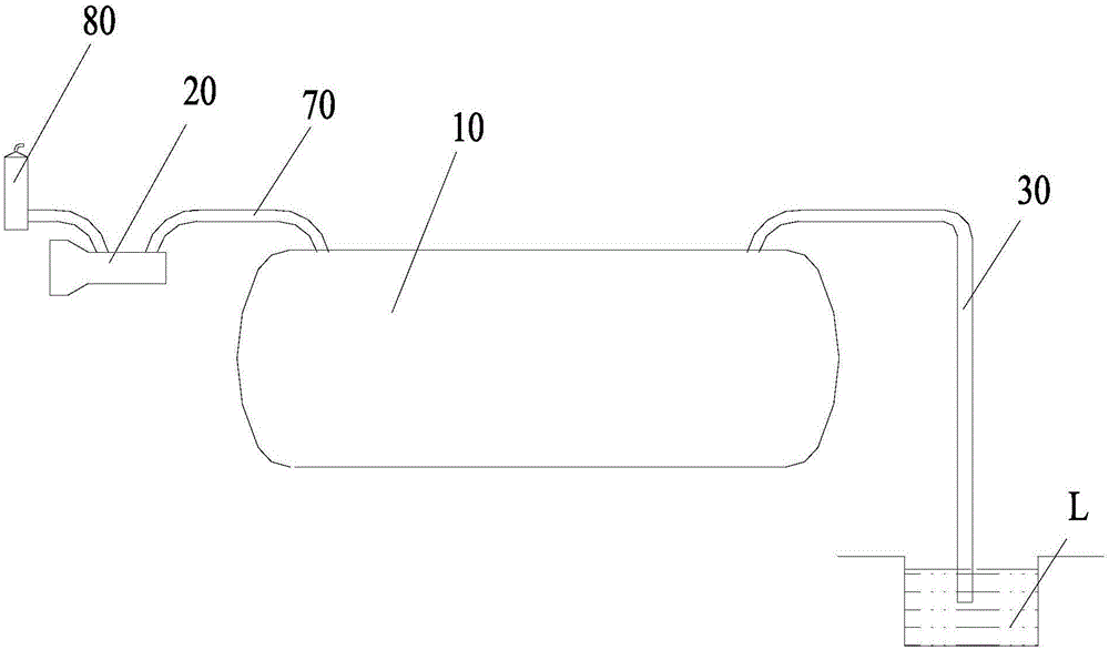
According to the principle of atmospheric pressure and the limit value of the vacuum degree that can be realized by the vacuum pump 20, it is generally considered that the limit value of the vacuum degree in the sewage tank 10 is 93%, and then the maximum suction height that can be achieved by the sewage suction pipe 30 during suction is 9.3m, when the position of the suctioned dirt is too low or the actual vacuum degree in the sewage tank 10 is smaller, it is impossible to complete the operation through negative pressure suction
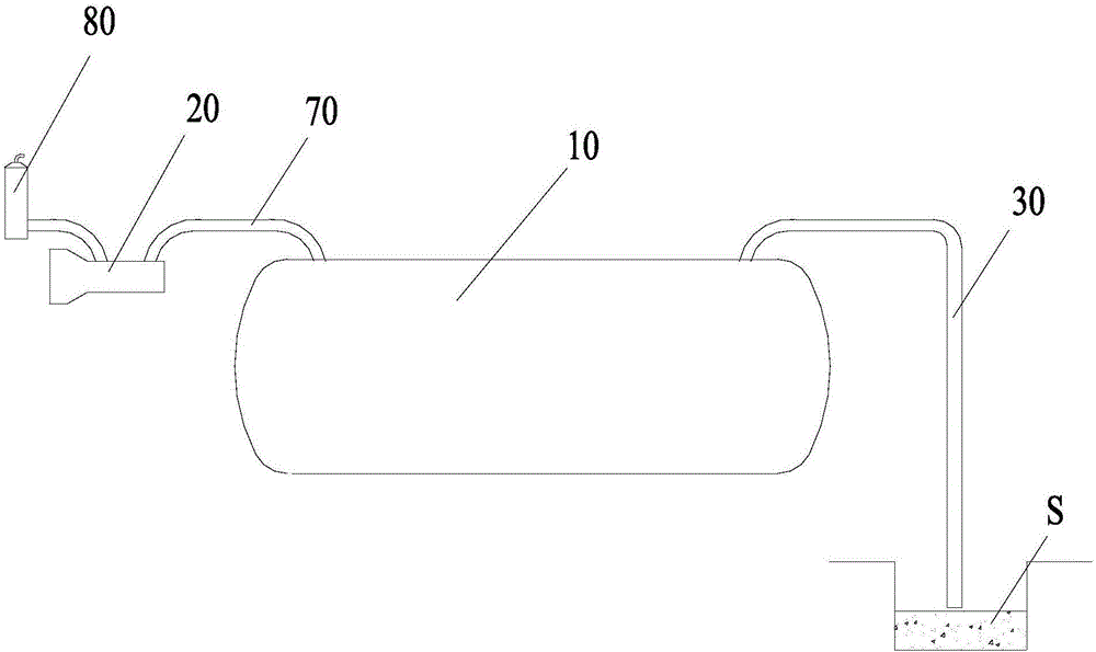
and, if figure 2 As shown, when using a sewage suction truck to suck solid waste S, since the port of the sewage suction pipe 30 cannot form a closed space as inserted below the liquid surface, the vacuum degree in the sewage tank 10 cannot be established, so it cannot be realized. Negative pressure suction
In addition, due to the high density of the solid waste, it is impossible to send the solid waste into the sewage tank 10 only by using the negative pressure suction of the atmospheric pressure.
[0003] Therefore, the existing negative pressure dirt suction has the problem that the suction height difference cannot be too large and solid dirt cannot be sucked

Method used


Image

  • Suction sewage equipment, suction sewage truck and suction sewage method
  • Suction sewage equipment, suction sewage truck and suction sewage method
  • Suction sewage equipment, suction sewage truck and suction sewage method

Examples


Embodiment Construction

[0023] Specific embodiments of the present invention will be described in detail below in conjunction with the accompanying drawings. It should be understood that the specific embodiments described here are only used to illustrate and explain the present invention, and are not intended to limit the present invention.

[0024] In the present invention, in the case of no contrary description, the used orientation words such as "up, down, left and right" usually refer to the up, down, left and right shown in the accompanying drawings; "inside and outside" Refers to the inside and outside of the outline of each part itself.

[0025] According to one aspect of the present invention, a kind of sewage suction equipment is provided, wherein, described sewage suction equipment comprises sewage tank 10, is used for the vacuum pump 20 of described sewage tank 10 (vacuum pump 20 can be connected to sewage tank 10 through vacuum pipe 70 and pass through The muffler 80 discharges the extra...


PUM


Abstract

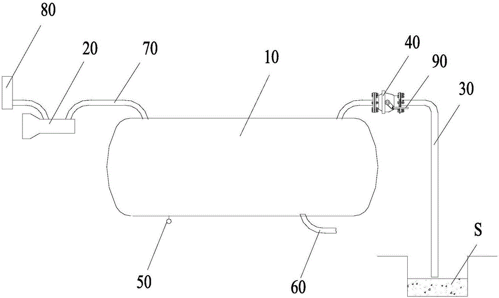
The invention relates to the field of environment sanitation, and discloses suction sewage equipment, a suction sewage truck and a suction sewage method. The suction sewage equipment comprises a sewage tank (10), a vacuum pump (20) for the sewage tank (10), and a suction sewage pipe (30) communicating with the sewage tank (10), wherein a port for controlling the suction sewage pipe (30) and a valve (40) communicating with the sewage tank (10) are arranged on the suction sewage pipe (30). According to the suction sewage equipment disclosed by the invention, the valve is opened when the degree of vacuum in the sewage tank reaches a predetermined value, a large pressure difference is generated at the port of the suction sewage pipe instantly and a strong air flow is formed, so that the sewage is conveyed into the sewage tank by the air flow, and a convey height difference generated in the manner, which is greater than that generated through the negative pressure suction is achieved.

Description

technical field [0001] The invention relates to the field of sanitation, in particular to a sewage suction device, a sewage suction vehicle and a sewage suction method. Background technique [0002] Existing sewage suction vehicles all use negative pressure to suck sewage, specifically, such as figure 1 , The sewage suction truck includes a sewage tank 10, a vacuum pump 20 for the sewage tank 10 (the vacuum pump 20 is connected to the sewage tank 10 through a vacuum tube 70 and discharges the extracted air into the atmosphere through a muffler 80) and a sewage suction tank communicated with the sewage tank 10. Tube 30. During operation, it is necessary to insert the port of the sewage suction pipe 30 under the liquid surface of the liquid sewage L. According to the principle of atmospheric pressure and the limit value of the vacuum degree that can be realized by the vacuum pump 20, it is generally considered that the limit value of the vacuum degree in the sewage tank 10 i...

Claims


Application Information

Patent Timeline
IPC IPC(8): E01H1/08
CPCE01H1/0836
Inventor 傅立荣
Owner ZOOMLION ENVIRONMENTAL IND CO LTD
Learn More