Flue gas recirculation combustion chamber with variable swirl

A technology of recirculation combustion chamber and combustion chamber, which is applied in combustion chamber, continuous combustion chamber, combustion method, etc., can solve the problems that emission parameters cannot be guaranteed, maintained at design strength, and flue gas return flow cannot be guaranteed.

Active Publication Date: 2021-02-19
HARBIN ENG UNIV
View PDF6 Cites 0 Cited by
  • Summary
  • Abstract
  • Description
  • Claims
  • Application Information

AI Technical Summary

Problems solved by technology

[0002] In the traditional combustion chamber structure, the swirl intensity corresponds to the swirler structure one by one. After the combustion chamber is designed, even if it operates in different working conditions, the swirl intensity can only be maintained at the design strength, and cannot be adjusted according to the working conditions. Change free adjustment
Under the condition of strong swirl intensity, the internal circulation of the flue gas is strong, and the strong swirl flow entrains the downstream flue gas to reduce the oxygen concentration in the main combustion area, thereby reducing the combustion temperature in the main combustion area to achieve the goal of low emissions. However, when the swirl intensity is weak, the flue gas return flow cannot be guaranteed, and the emission parameters cannot be guaranteed

Method used


Image

  • Flue gas recirculation combustion chamber with variable swirl
  • Flue gas recirculation combustion chamber with variable swirl
  • Flue gas recirculation combustion chamber with variable swirl

Examples


Embodiment Construction

[0016] The present invention will be further described in detail below in conjunction with the accompanying drawings and specific embodiments.

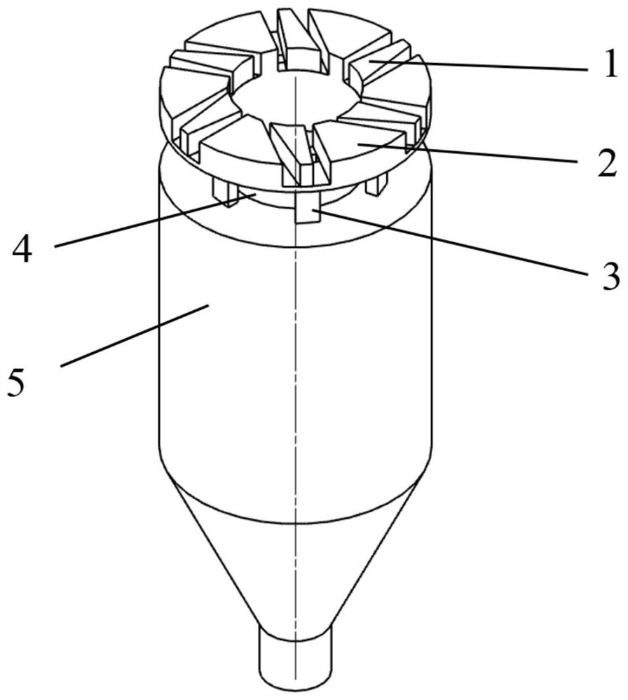
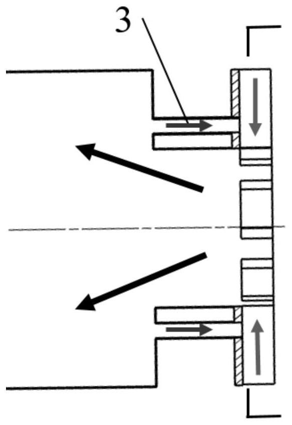
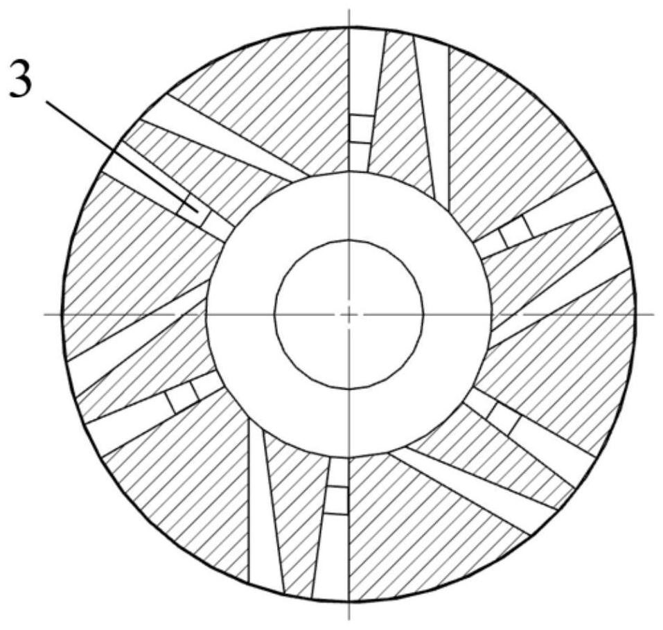
[0017] Such as Figure 1-4 As shown, a flue gas return combustion chamber with variable swirl flow includes five parts: fixed swirl blade 2, moving swirl blade 1, flue gas return channel 3, combustion chamber throat 4, and combustion chamber cavity 5 . The fixed swirler consists of six fixed swirler blade modules of the same shape and size, which are fixed to the combustion chamber by welding or other methods. Each fixed swirler blade module has two arc sides, one radial side and one Tangential side, the inner arc side 14 is the same as the inner diameter of the combustion chamber throat 4, wherein the extension line of the radial side 11 passes through the center of the swirler, and the radial direction of the tangential side 13 and its adjacent fixed swirler blade module The side 11 is parallel; the mobile swirler is composed of s...


PUM


Abstract

The invention provides a flue gas backflow combustion chamber with variable rotational flow, which comprises a combustion chamber cavity, a combustion chamber throat arranged at the upper end of the combustion chamber cavity and a swirler blade structure arranged at the upper end of the combustion chamber throat, wherein the swirler blade structure comprises fixed swirler blades arranged at equalintervals, blade flow channels are formed between the fixed swirler blades, each blade flow channel is provided with a movable swirler blade, and a flue gas backflow channel is arranged between each blade flow channel and the combustion chamber cavity. According to the invention, the purpose of low emission can be achieved no matter under a high rotational flow condition or a low rotational flow condition.

Description

technical field [0001] The invention relates to a flue gas recirculation combustion chamber, in particular to a combustion chamber structure capable of adjusting swirl intensity and flue gas return flow rate, and achieving the goal of low emission no matter in high swirl flow condition or low swirl flow condition. Background technique [0002] In the traditional combustion chamber structure, the swirl intensity corresponds to the swirler structure one by one. After the combustion chamber is designed, even if it operates in different working conditions, the swirl intensity can only be maintained at the design strength, and cannot be adjusted according to the working conditions. Changes can be adjusted freely. Under the condition of strong swirl intensity, the internal circulation of the flue gas is strong, and the strong swirl flow entrains the downstream flue gas to reduce the oxygen concentration in the main combustion area, thereby reducing the combustion temperature in th...

Claims


Application Information

Patent Timeline
Patent Type & Authority Patents(China)
IPC IPC(8): F23R3/58
CPCF23R3/58
Inventor 刘潇张志浩刘刚游滨川陆景贺刘恩惠
Owner HARBIN ENG UNIV
Why Eureka
Try Eureka