Piezoelectric inkjet head and printing device comprising same

An ink head and nozzle technology, applied in the fields of printing equipment and piezoelectric inkjet heads, can solve the problems of easy blockage of fluid grooves and/or micro-nozzle holes, low working efficiency of piezoelectric inkjet heads, and small space for material selection, etc. Achieve the effect of improving work efficiency, low processing cost, and large space for material selection

Active Publication Date: 2014-08-06
PAIHE SCI & TECH HLDG CO LTD BEIJING
View PDF7 Cites 5 Cited by
  • Summary
  • Abstract
  • Description
  • Claims
  • Application Information

AI Technical Summary

Problems solved by technology

[0005] The invention provides a piezoelectric inkjet head and a printing device including the piezoelectric inkjet head, which effectively solves the problem of low working

Method used


Image

  • Piezoelectric inkjet head and printing device comprising same
  • Piezoelectric inkjet head and printing device comprising same
  • Piezoelectric inkjet head and printing device comprising same

Examples


Example Embodiment

[0035] In order to make the technical problems, technical solutions and advantages to be solved by the embodiments of the present invention clearer, the following will describe in detail with reference to the drawings and specific embodiments.

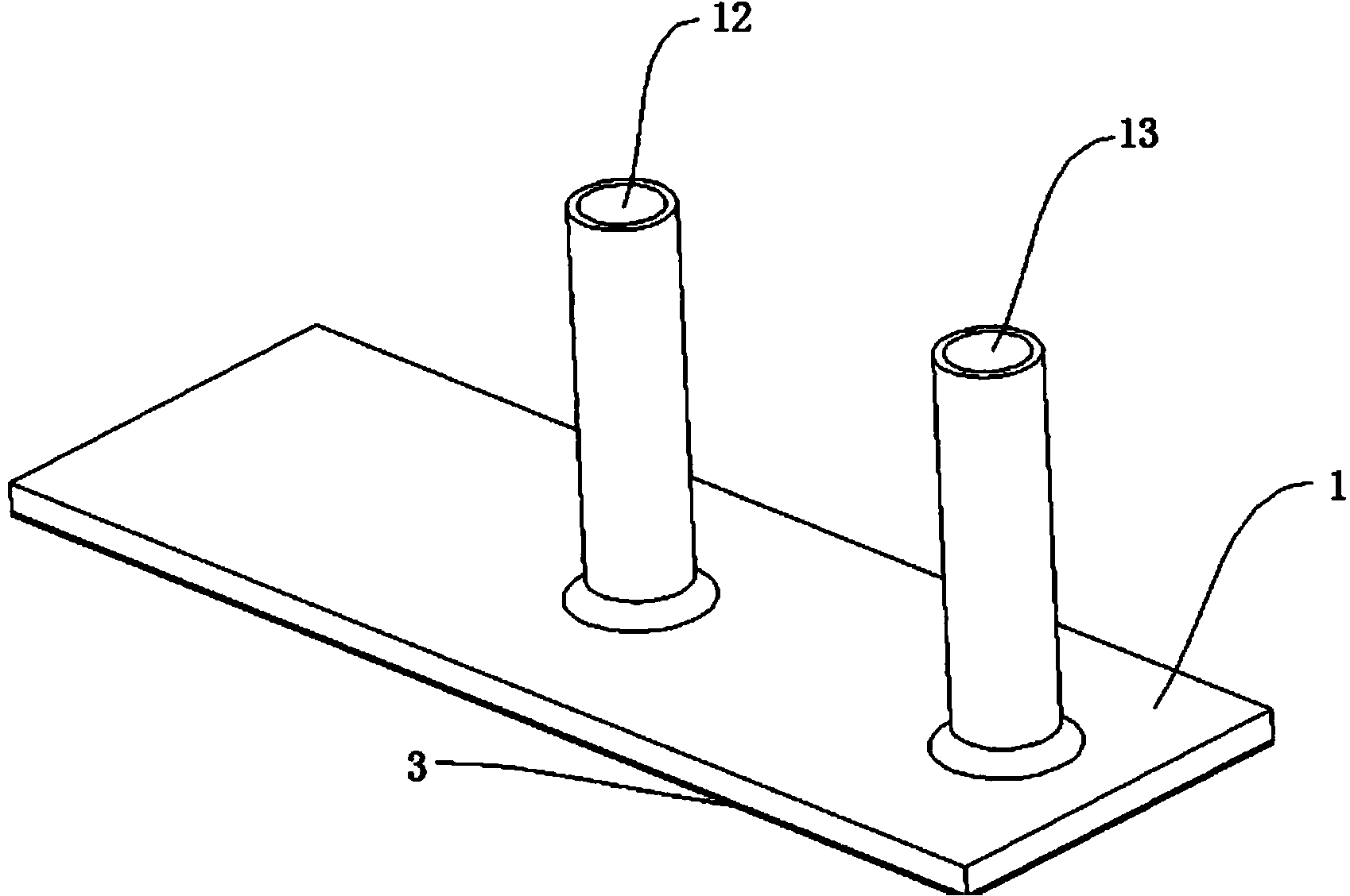
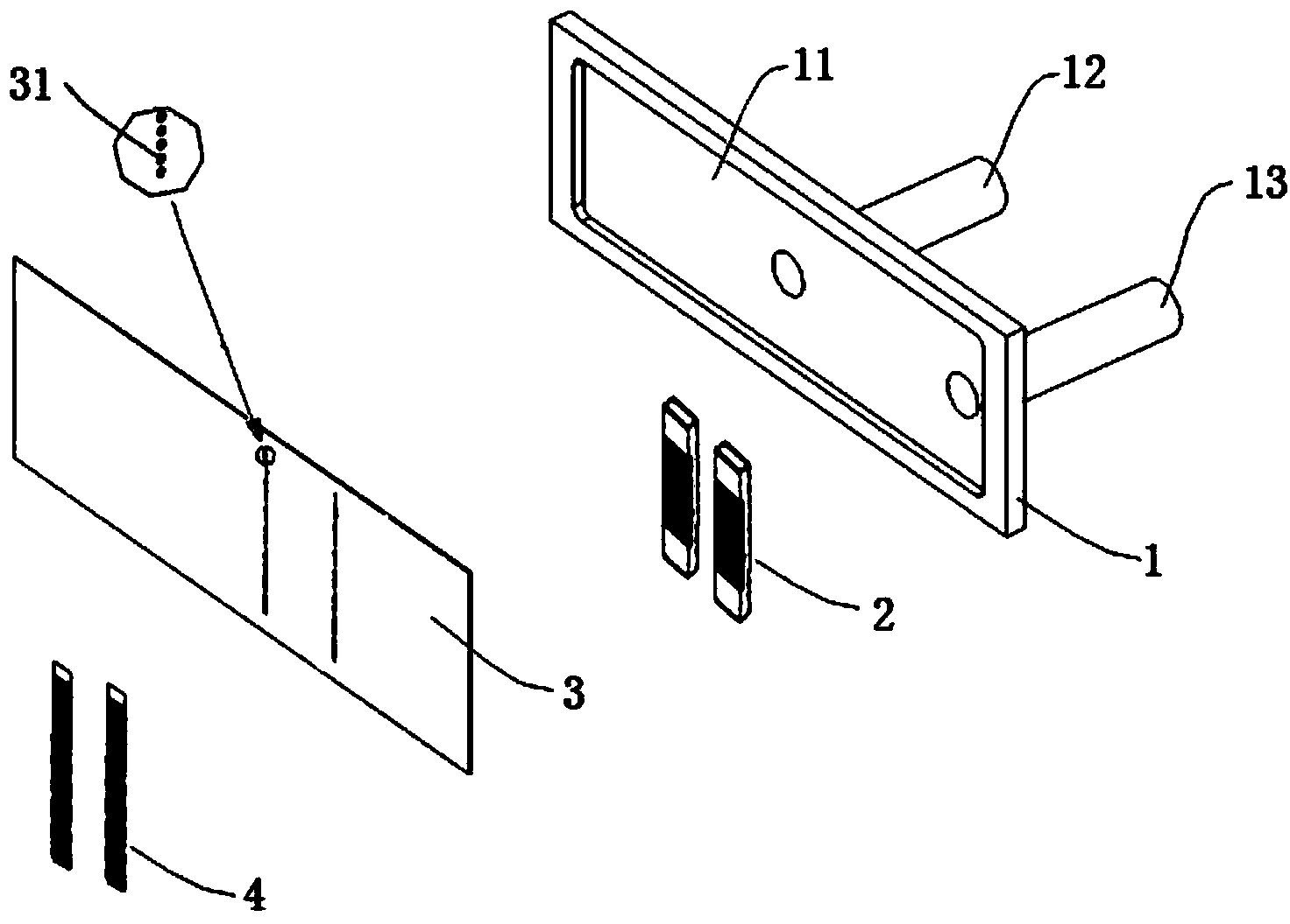
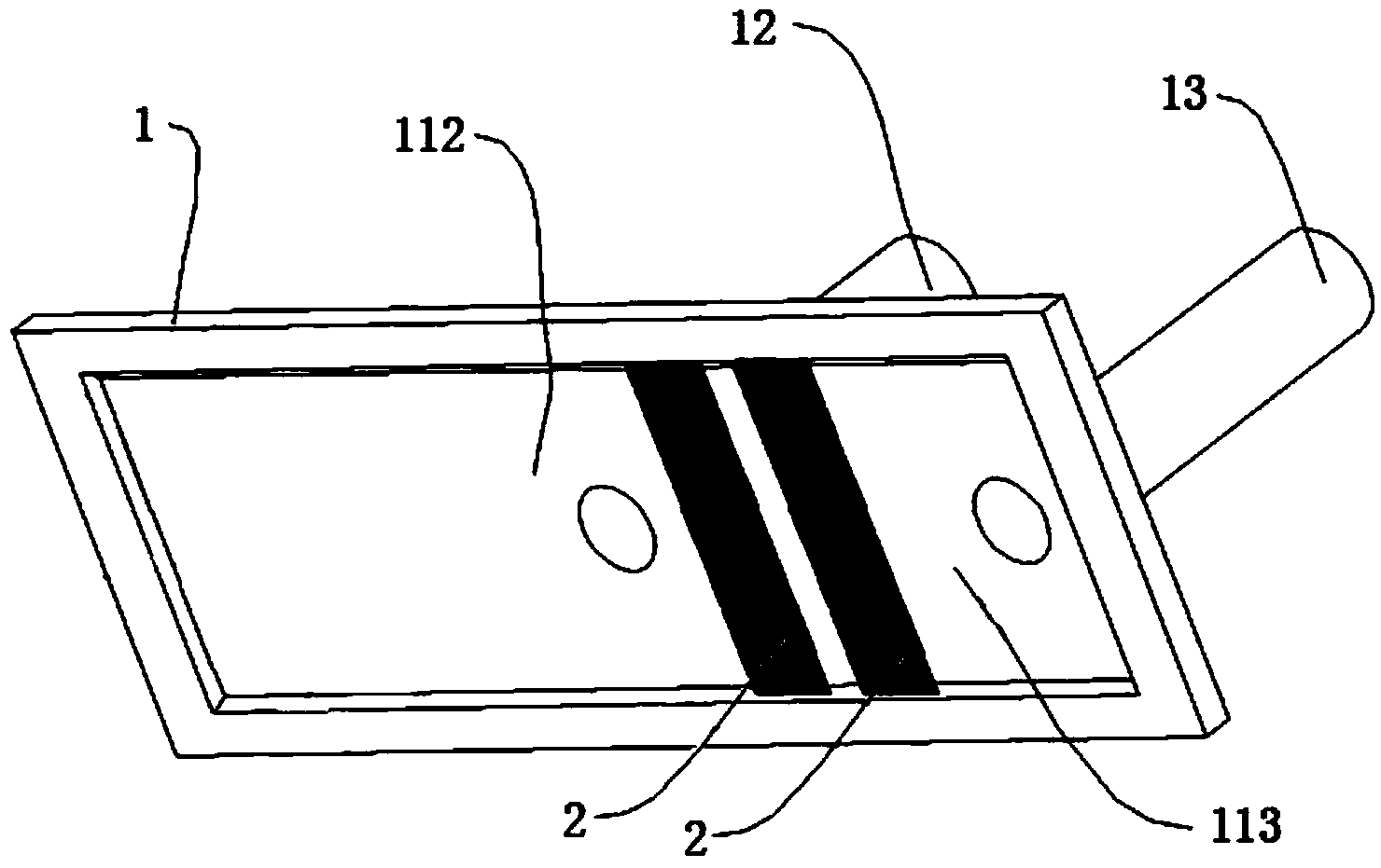
[0036] In one aspect, the present invention provides a piezoelectric inkjet head, such as Figure 1 to Figure 7 As shown, it includes a nozzle base 1, a fluid tank plate 2, a nozzle plate 3 (or 3’), a piezoelectric ceramic driver 4 and a drive circuit device (not shown), wherein:

[0037] There is a groove on the lower end surface of the nozzle base 1, and the nozzle plate 3 (or 3') is covered on the groove to form an ink chamber 11, and the upper end surface of the nozzle base 1 is provided with ink communicating with the ink chamber 11. The inflow pipeline 12, the ink outflow pipeline 13, and the nozzle base 1 can be injection molded, which is completed at one time, and the process is simple and reliable;

[0038] The fluid tank pla...


PUM

PropertyMeasurementUnit
Thicknessaaaaaaaaaa
Thicknessaaaaaaaaaa
Diameteraaaaaaaaaa

Abstract

The invention discloses a piezoelectric inkjet head and a printing device comprising the piezoelectric inkjet head and belongs to the technical field of inkjet printing. The piezoelectric inkjet head comprises a spray head base, a fluid groove plate, a spray nozzle plate, a piezoelectric ceramic driver and a driving circuit device. The spray head base comprises an ink cavity, an ink inflow pipeline and an ink outflow pipeline. A plurality of fluid grooves are formed in the fluid groove plate, and the fluid groove plate divides the ink cavity into an ink inflow cavity and an ink outflow cavity. A plurality of micro-jet holes are formed in the spray nozzle plate, and each micro-jet hole corresponds to the position of the concave part of one fluid groove. The piezoelectric ceramic driver comprises a plurality of piezoelectric ceramic micro-units, and each piezoelectric ceramic micro-unit corresponds to the position of the concave part of one fluid groove. The driving circuit device is electrically connected with the piezoelectric ceramic driver. The piezoelectric inkjet head effectively solves the problems that an existing piezoelectric inkjet head is low in working efficiency, small in material selection space and high in machining cost and fluid grooves and/or micro-jet holes are blocked easily.

Description

technical field [0001] The invention relates to the technical field of inkjet printing, in particular to a piezoelectric inkjet head and printing equipment including the piezoelectric inkjet head. Background technique [0002] Piezoelectric inkjet head, as the core of ceramic inkjet printers, occupies the highest cost, is the most important, and has the highest technical content. It is blank in China from research and development to manufacturing, and is completely dependent on imports. Most of these piezoelectric inkjet heads use the piezoelectric ceramic groove cutting process, through the shear deformation of the piezoelectric ceramic groove wall, the ink extrusion action is realized, but the movement of the groove wall will affect the adjacent groove wall. Injection action, so the micro-orifice plate of the existing piezoelectric inkjet head is generally designed according to a group of three micro-orifices. less efficient. [0003] The ejection action of the above-men...

Claims


Application Information

Patent Timeline
IPC IPC(8): B41J2/14
Inventor 黄大任崔宏超
Owner PAIHE SCI & TECH HLDG CO LTD BEIJING
Why Eureka
Try Eureka