Efficient energy-saving glass kiln

A glass furnace, energy-saving technology, applied in glass furnace equipment, glass manufacturing equipment, dispersed particle filtration, etc., can solve the problems of high energy consumption, improve processing quality, improve heating efficiency and effect, and reduce bubble generation Effect

Inactive Publication Date: 2021-07-20
蚌埠鑫尚新材料有限公司
View PDF0 Cites 0 Cited by
  • Summary
  • Abstract
  • Description
  • Claims
  • Application Information

AI Technical Summary

Problems solved by technology

[0004] The purpose of the present invention is to solve the problem of large energy consumption in the prior art, and propose a high-efficiency and energy-saving glass furnace

Method used


Image

  • Efficient energy-saving glass kiln
  • Efficient energy-saving glass kiln
  • Efficient energy-saving glass kiln

Examples


Embodiment

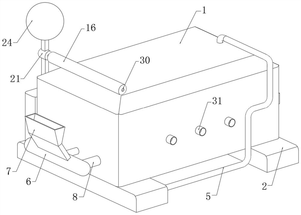
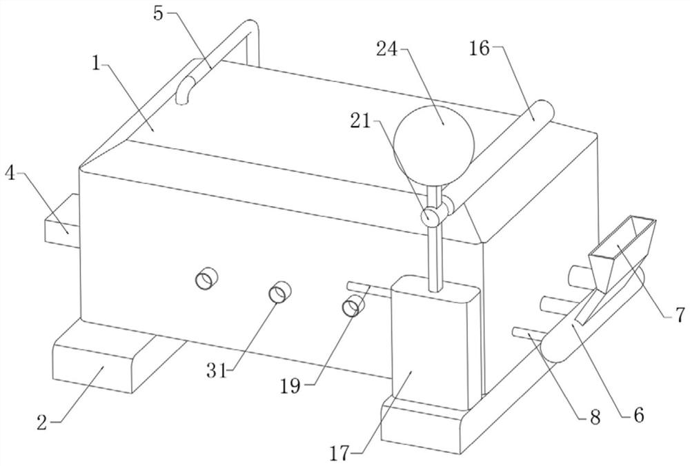
[0032] Refer Figure 1-6 A high-efficiency energy-saving glass kiln, including the furnace body 1, and the bottom of the furnace body 1 fixes two symmetric base 2, one side inner wall of the furnace body 1 fixes the transfer chamber 3, the internal setting of the transfer chamber 3 There is a pretreatment mechanism, and the inner wall of the other side of the furnace body 1 is inserted with an effluent tube 4, and the outer wall provided with the side of the shift chamber 3 is provided with a feed allocation mechanism. The upper end of the furnace is inserted with a exhaust pipe. 5, the other end of the exhaust pipe 5 communicates with the base 2 adjacent the transfer chamber 3, and the inner portion of the furnace body 1 is provided with a jet heating mechanism, and the upper end of the base 2 of the transfer chamber 3 is fixed to the cooling box 17, the cooling box. The inner part of 17 is provided with a condensation recovery mechanism.

[0033] The pretreatment mechanism includ...

Embodiment 2

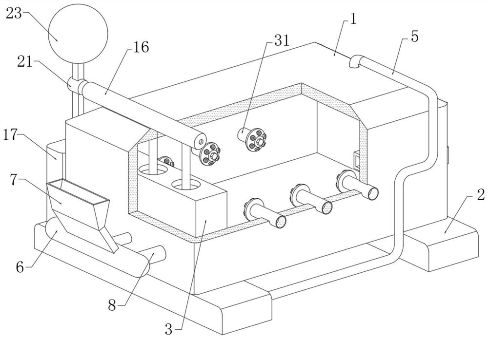
[0048] Refer Figure 7 The difference between the embodiment and the embodiment is different from the injection heating mechanism, and the injection heating mechanism includes a plurality of injection tubes 31 on both sides of the furnace body 1, and two injection tubes 31 on one side of the furnace body 1 On the side, three jet tubes 31, the five injection tube 31 is displaced, that is, the injection range of the respective injection tube 31 does not overlap, the injection tube 31 of the intermediate position impinges the gap position of the two injection tube 31, the furnace body 1. The inner bottom rotation is rotated with three stirring shafts 32, each circumferential side wall of each agitating shaft 32 fixedly coupled with a plurality of drive leafs 33, and a plurality of stirring rods 34 are fixed in the lower circumferential side wall of each agitating shaft 32. The drive leaf 33 is located above the fluid liquid surface, and the area is larger than the reception impact, an...


PUM


Abstract

A disclosed efficient energy-saving glass kiln comprises a kiln body, two symmetrically-arranged bases are fixed to the bottom of the kiln body, a transfer chamber is fixed to the inner wall of one side of the kiln body, a pretreatment mechanism is arranged in the transfer chamber, and a discharging pipe is inserted into the inner wall of the other side of the kiln body; and a feeding distribution mechanism is arranged on the outer wall of the side, provided with the transfer chamber, of the furnace body, smoke exhaust pipes are inserted into the upper end of the furnace body, and the other ends of the smoke exhaust pipes communicate with the interiors, close to the transfer chamber, of the bases. The kiln has the advantages that the feeding distribution mechanism is arranged, the pipe diameters of three material injection pipes are different, so that the amount of raw materials added into three transfer tanks is different and gradually reduced, and in cooperation with continuous reduction of heat absorbed in the flue gas transfer process, the flue gas waste heat obtained in the three transfer tanks is greatly improved; and the raw material quantity required to be subjected to waste heat treatment can be matched with each other, so that effective waste heat of the raw materials is ensured.

Description

Technical field [0001] The present invention relates to the field of glass production, in particular, to a highly efficient energy-saving glass kiln. Background technique [0002] Glass is amorphous inorganic non-metallic material, widely used in buildings, is used to heat through the wind, belonging to a mixture, a mixture, an oxide or salt mixed with a metal, showing colored glass, and by physical or chemical methods Temperature glass, etc., sometimes some transparent plastic is also referred to as organic glass, and glass products are often melted through glass kiln during production, and the glass kiln is required for glass manufacturing industries; [0003] In the glass treatment, it is usually directly fired, and the glass kiln is also formed in a refractory material. In order to reduce production costs, it is usually used as a fuel, so this method is to bring more flue gas, and this Some flue gals still have more heat unused in emissions. Existing equipment is only purifie...

Claims


Application Information

Patent Timeline
Patent Type & Authority Applications(China)
IPC IPC(8): C03B5/00C03B5/16C03B5/187B01D46/00B01D46/14B01D46/42
CPCB01D46/0056B01D46/14B01D46/4218C03B5/00C03B5/16C03B5/187
Inventor 崔金荣张鹏温坤
Owner 蚌埠鑫尚新材料有限公司
Why Eureka
Try Eureka