Gas exhaust device used for closed type hydraulic system

A technology of hydraulic system and exhaust device, applied in the direction of fluid pressure actuating device, fluid pressure actuating system components, mechanical equipment, etc., can solve problems such as affecting the life of hydraulic components, cavitation, reducing system reliability, etc. Longevity, effect of reducing cavitation intensity

Inactive Publication Date: 2017-02-22
CSIC NO 710 RES & DEV INST
View PDF10 Cites 3 Cited by
  • Summary
  • Abstract
  • Description
  • Claims
  • Application Information

AI Technical Summary

Problems solved by technology

[0002] At present, the buoyancy drive unit used for deep-sea submersibles to realize up and down movement generally adopts a closed hydraulic system. Due to the system assembly and the hydraulic oil itself, it is easy to mix air into the hydraulic system; the existence of air in the hydraulic oil can easily make the closed hydraulic system Cavitation occurs when the hydraulic system works under high pressure and deep depth, which affects the life of hydraulic components and reduces the reliability of the system; the traditional hydraulic system exhaust method can only evacuate the gas that has not dissolved in the oil in the system, but cannot effectively discharge the gaps in the system Gas with medium and small bubbles and a small amount of gas dissolved in hydraulic oil under normal pressure

Method used


Image

  • Gas exhaust device used for closed type hydraulic system

Examples


Embodiment Construction

[0015] The present invention will be described in detail below with reference to the accompanying drawings and examples.

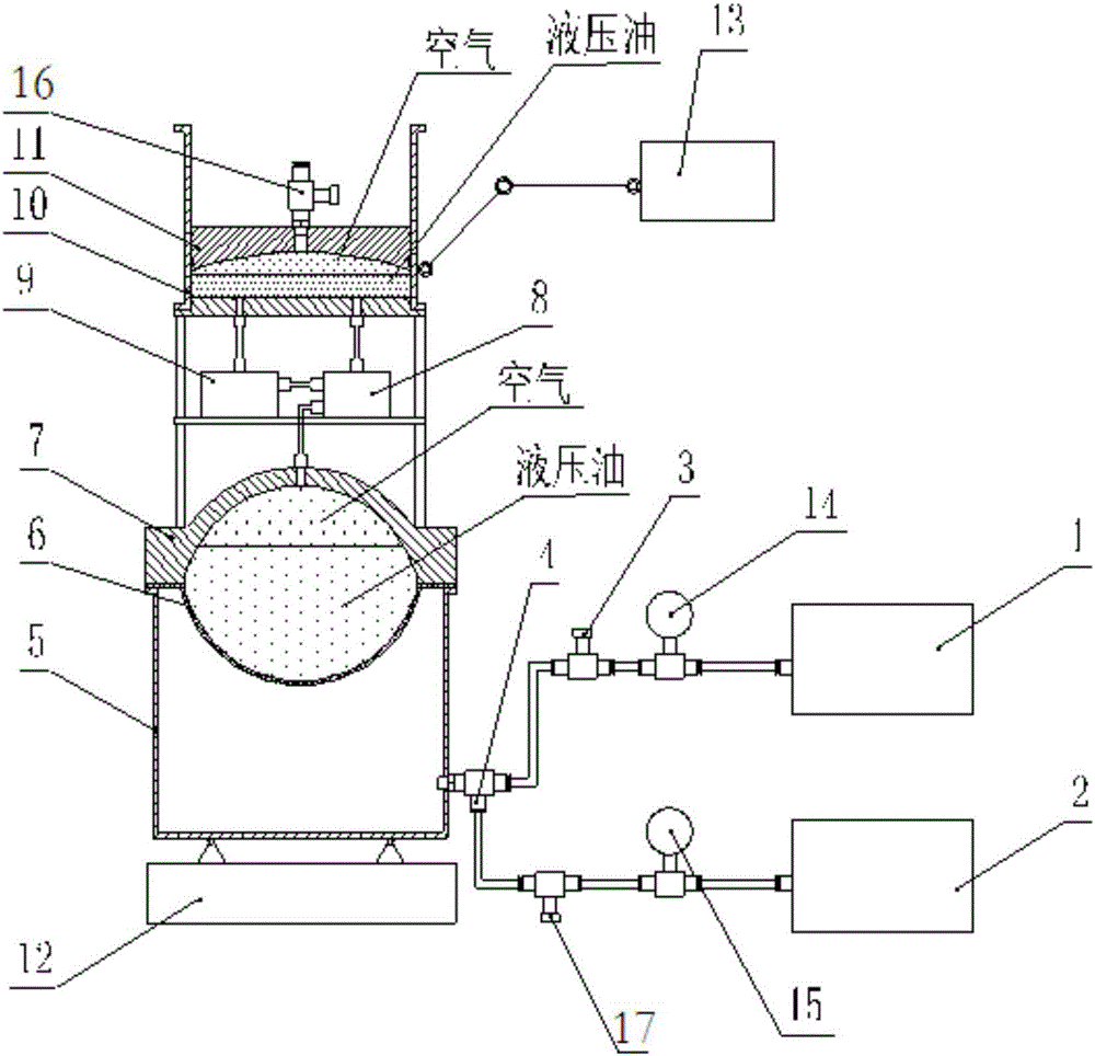
[0016] The invention provides an exhaust device for a closed hydraulic system, see the attached figure 1 , including: vacuum pump 1, air compressor 2, second stop valve 3, third stop valve 17, tee joint 4, sealing cover 5, swing mechanism 12, excitation mechanism 13, vacuum pressure gauge 14 and pressure gauge 15;

[0017] Its peripheral equipment is a closed hydraulic system, which includes: oil bag 6, pressure-resistant cover 7, valve group 8, hydraulic pump 9, oil tank 10, piston 11 and first stop valve 16; the bottom surface of the oil tank 10 is respectively provided with oil outlet and oil inlet; the oil bag 6 is docked with the pressure-resistant cover 7 to form a closed cavity, and hydraulic oil is housed in the closed cavity; the hydraulic pump 9 communicates with the closed cavity through the valve group 8; the oil tank 10 is equipped with Hydra...


PUM


Abstract

The invention discloses a gas exhaust device used for a closed type hydraulic system, and belongs to the technical field of hydraulic systems. The gas exhaust device comprises a vacuum pump, an air compressor, a second stop valve, a third stop valve, a three-way joint, a sealing cover, a swing mechanism and an incentive mechanism, wherein the incentive mechanism is mounted on the side surface of the oil tank; the open end of the sealed cover is in butt joint with an oil bag, and is closed to form a sealed cavity; the closed end of the sealed cavity is connected with the swing mechanism through a ball head hinge; the three-way joint is mounted on the side surface of the sealing cover; the vacuum pump and the air compressor are separately connected with the two ends of the three-way joint on the side surface of the sealing cover through pipelines; and the stop valves are separately connected on pipelines for connecting the vacuum pump, the air compressor and the three-way joint. According to the gas exhaust device disclosed by the invention, air in hydraulic oil is separated out in a vacuum-pumping mode, and air is exhausted out of the system by uniformly extruding under external pressure; and the swing mechanism is matched with the incentive mechanism for use, so that air bubbles in seams are exhausted of the system, and therefore, gas in the closed type hydraulic system is purified.

Description

technical field [0001] The invention belongs to the technical field of hydraulic systems, and in particular relates to an exhaust device for a closed hydraulic system. Background technique [0002] At present, the buoyancy driving unit used for the deep-sea submersible to realize the up and down movement generally adopts a closed hydraulic system. Due to the system assembly and the hydraulic oil itself, it is easy to mix air into the hydraulic system; the existence of air in the hydraulic oil can easily make the closed hydraulic system Cavitation occurs when the hydraulic system works under high pressure and depth, which affects the life of hydraulic components and reduces the reliability of the system; the traditional hydraulic system exhaust method can only evacuate the gas that has not dissolved in the oil in the system, but cannot effectively discharge the gaps in the system Medium and small gas bubbles and a small amount of gas dissolved in hydraulic oil under normal pr...

Claims


Application Information

Patent Timeline
Patent Type & Authority Applications(China)
IPC IPC(8): F15B21/04
CPCF15B21/044
Inventor 冀功祥刘方蒋平方巍吴文辉
Owner CSIC NO 710 RES & DEV INST
Why Eureka
Try Eureka