A Split Type Springless Overrunning Clutch

An overrunning clutch, no spring technology, used in clutches, one-way clutches, mechanical equipment, etc., can solve the problems of inconvenient application, low reliability, complex structure, etc., and achieve simple structure, high reliability, quick engagement and quick separation. Effect

Active Publication Date: 2018-10-09
BEIJING RES INST OF PRECISE MECHATRONICS CONTROLS +1
View PDF7 Cites 0 Cited by
  • Summary
  • Abstract
  • Description
  • Claims
  • Application Information

AI Technical Summary

Problems solved by technology

[0002] Most of the existing overrunning clutches have an integrated structure, which is suitable for occasions where the driving and driven shafts are located in a single component that is not often disassembled. For the occasions where the driving and driven shafts belong to two independent components, it is inconvenient to apply; the existing overrunning clutch Clutches mostly use return springs with complex structures, resulting in low reliability

Method used


Image

  • A Split Type Springless Overrunning Clutch
  • A Split Type Springless Overrunning Clutch
  • A Split Type Springless Overrunning Clutch

Examples


Embodiment 1

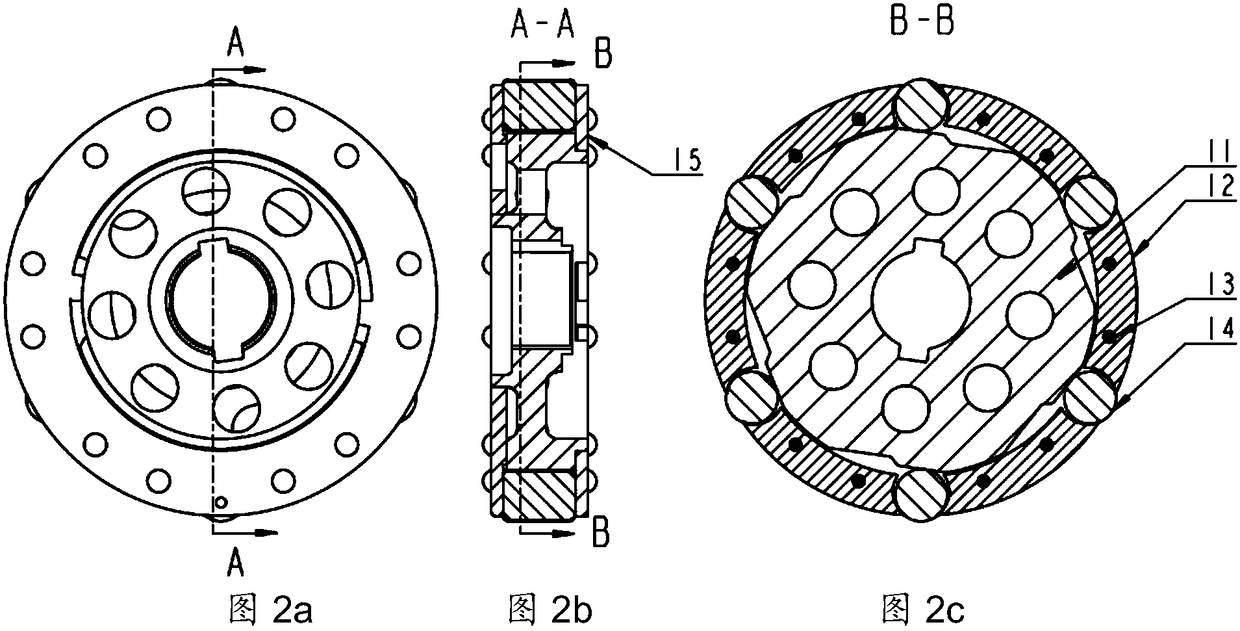
[0045] Such as figure 2 As shown, the support ring 12 in this embodiment includes a central stepped hole and six blind holes, the cam 11 is located in the central stepped hole of the support ring 12, and is supported by the steps, and the six rolling rods 14 are respectively located on the six corners of the support ring 12. In a blind hole; then the cam 11 and the rolling rod 14 are packaged inside the support ring 12 through the cover plate 15, and the cover plate 15 and the support ring 12 are linked by rivets 13, the cam 11, the support ring 12, the rivets 13, The rolling rod 14 and the cover plate 15 together form the clutch main body 1 .

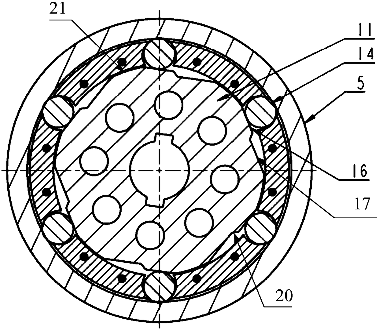
[0046] Such as Figure 6 As shown, in this embodiment, there are six working areas and non-working areas, which are evenly distributed on the circumference of the cam 11. The six working areas have the same structural shape, and the six non-working areas 21 are also six sections with the same structural shape. arc. The wrap angle δ...


PUM


Abstract

The invention provides a split type springless overrunning clutch which comprises a clutch body and a clutch cap, wherein the clutch body is mounted on a hydraulic motor shaft, and rotates synchronously along with the hydraulic motor shaft; the clutch cap is mounted on an electric motor shaft, and rotates synchronously along with the electric motor shaft; the cutch body comprises a cam, a backing ring and N rolling rods; the cam is located in the middle of the backing ring; the N rolling rods are located at the outer part of the cam, and are uniformly distributed along the edge of the backing ring; the cam adopts a circular structure; N working areas and N non-working areas are alternately distributed on the outer surface of the cam; the outer surface of each non-working area is matched with the inner surface of the edge of the backing ring; each working area comprises a meshing area and a separating area; the meshing areas are connected with the separating areas through transition slopes; the rolling rods are in contact with the meshing areas to realize meshing between the clutch body and the clutch cap; and the rolling rods are in contact with the separating areas to realize separation. Meshing and separating are realized by means of the inertia of the rolling rods and relative movement between the cam and the rolling rods, and the split type springless overrunning clutch is simple in structure, high in reliability, and convenient to disassemble, assemble and use.

Description

technical field [0001] The invention relates to a split type overrunning clutch, in particular to a split type springless overrunning clutch. Background technique [0002] Most of the existing overrunning clutches have an integrated structure, which is suitable for occasions where the driving and driven shafts are located in a single component that is not often disassembled. For the occasions where the driving and driven shafts belong to two independent components, it is inconvenient to apply; the existing overrunning clutch Clutches mostly use return springs with complex structures, resulting in low reliability. [0003] The new-generation launch vehicle servo mechanism integrates two modes of ground testing and space flight. The driving components of the two modes are electric motors and hydraulic motors. In order to realize automatic switching between the two modes, and in the space flight mode To achieve the transmission of the output power of the hydraulic motor, a new...

Claims


Application Information

Patent Timeline
Patent Type & Authority Patents(China)
IPC IPC(8): F16D41/067
CPCF16D41/067
Inventor 于斌刘会祥丁闪朱熠王伟肖守敏
Owner BEIJING RES INST OF PRECISE MECHATRONICS CONTROLS
Why Eureka
Try Eureka