Electronic control variable-damping rotation hydraulic damper

A hydraulic damper and variable technology, applied in the direction of liquid shock absorber, shock absorber, shock absorber, etc., can solve the problems of insufficient compact structure of proportional servo control scheme and high cost of proportional valve control, and achieve compact structure and convenient The effect of installation

Inactive Publication Date: 2017-02-22
HUBEI UNIV OF AUTOMOTIVE TECH
View PDF11 Cites 11 Cited by
  • Summary
  • Abstract
  • Description
  • Claims
  • Application Information

AI Technical Summary

Problems solved by technology

Due to structural limitations, both the rotary vane damping scheme and the torsion-adjustable rotary damping scheme in the literature can only achieve damping loading in reciprocating rotation with a rotation angle of less than 360°, and the rotary hydraulic pump + damping hole proportional servo control scheme is not compact enough. And the cost of proportional valve control is high

Method used


Image

  • Electronic control variable-damping rotation hydraulic damper
  • Electronic control variable-damping rotation hydraulic damper
  • Electronic control variable-damping rotation hydraulic damper

Examples


Embodiment Construction

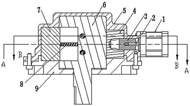
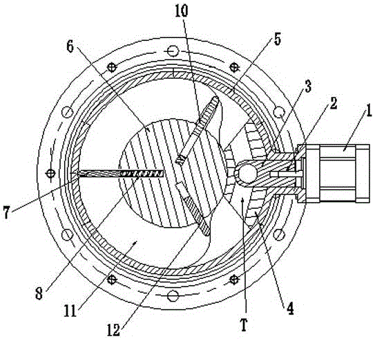
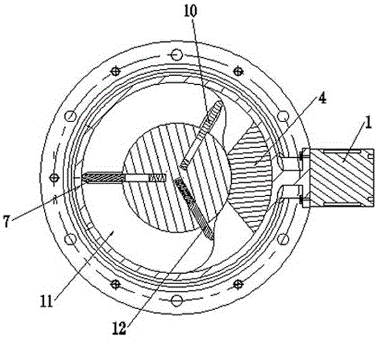
[0022] combine Figure 1-Figure 4 As shown, the present invention is further described as follows: an electronically controlled variable damping rotary hydraulic damper, including 3 vanes, a valve body 4, a valve core 3, a shaft 6, a housing 5, an end cover 9, a compression spring 8, a motor 1. The three blades are the first blade 7, the second blade 12, and the third blade 10. The end cover 9 is connected to the housing 5. The shaft 6 is located in the cavity between the end cover and the housing. The input of the shaft 6 protruding from the end cap,

[0023] A guide rail 11 is processed on the shell and the bottom cover. The minimum diameter of the guide rail 11 is equal to the outer diameter of the shaft. The maximum diameter of the guide rail 11 is equal to the diameter of the inner cavity of the housing. The arc with the largest diameter and the concentric arc with the smallest diameter are connected by a transition curve;

[0024] The first blade 7, the second blade 12...


PUM


Abstract

The invention relates to an electronic control variable-damping rotation hydraulic damper which comprises a motor, an outer shell, a blade, a valve element, a valve body, a shaft, a spring, a cover plate and the like. Due to the fact that a guide groove is formed in the middle shaft of the variable-damping rotation hydraulic damper, a guide rail is arranged on the shell, the blade automatically moves transversely in the radial direction along with the guide rail during rotation, the volume of driven liquid is changed, the liquid flows in a circulated manner through the valve element, and the function that the rotation angle of the damper is unlimited is achieved; and the valve element is driven by a step motor to rotate, so that the size of the drift diameter of a runner composed of the valve element and the valve body is variable, and the function of being adjustable in rotation damping is achieved.

Description

technical field [0001] The invention relates to a hydraulic damper, in particular to an electronically controlled damping rotary hydraulic damper, which belongs to the fields of automobiles and electromechanics. Background technique [0002] At present, hydraulic dampers are widely used in machinery, automobile and other industries to alleviate the impact caused by mechanical vibration. Common hydraulic dampers on automobiles are mainly cylinder-type hydraulic dampers with linear displacement changes, which are difficult to apply in rotating machinery. In order to increase the damping of the mechanism's rotation process, researchers have proposed magnetorheological schemes, rotational hydraulic damping schemes, etc. The magneto-rheological scheme is relatively expensive due to its complicated control. The common hydraulic damping schemes mainly include rotary vane damping scheme, rotary hydraulic pump + damping hole proportional servo control scheme, torque adjustable rota...

Claims


Application Information

Patent Timeline
Patent Type & Authority Applications(China)
IPC IPC(8): F16F9/12F16F9/44
CPCF16F9/125F16F9/446F16F2230/0005F16F2230/18
Inventor 赵慧勇王保华冯樱张光德石振曹杰陈小兵邓召文余颖宏喻超杨胡飞李娇万锐
Owner HUBEI UNIV OF AUTOMOTIVE TECH
Why Eureka
Try Eureka