Multi-unit collinear driving transmission

A multi-unit, transmission technology, applied in transmission parts, belts/chains/gears, mechanical equipment, etc., can solve the problems of high cost, complex structure, large mechanism, etc.

Inactive Publication Date: 2017-02-22
杭州市萧山区高级技工学校
View PDF4 Cites 2 Cited by
  • Summary
  • Abstract
  • Description
  • Claims
  • Application Information

AI Technical Summary

Problems solved by technology

[0003] The weight of the train is very large, and the moving train has a lot of kinetic energy. In order to ensure a smooth stop when braking, the train brake uses the air control air brake mechanism to perform air brake on the train, and the kinetic energy of the entire running is completely wasted. About the brake At present, the technology commonly used to recover the kinetic energy of the train is to recover the electric energy through the generator. However, the kinetic energy of the train is so large that in order to fully recover the kinetic energy, it is necessary to increase the input speed of the generator through the gearbox to a large extent. It may be necessary to increase the speed of the train shaft. 10-20 times or even more, but when the transmission ratio of the gearbox is very large, the whole mechanism is required to be very large, and the whole structure will be very complicated with lubrication, and the cost will be very high. If it is installed on each carriage, it will be It is not a small expense, so it will be necessary to invent a transmission with a small size and a large transmission ratio

Method used


Image

  • Multi-unit collinear driving transmission
  • Multi-unit collinear driving transmission
  • Multi-unit collinear driving transmission

Examples


specific Embodiment approach

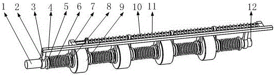
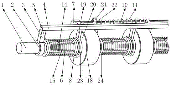
[0039] The specific implementation method is as follows: at first, the four transmission shafts 37 all stretch out of the inner ring tooth support ring 42, and are respectively in contact with the circular plate in front. At this time, the input shaft 1 drives the output shaft 12 to rotate after being transmitted by the four transmission shafts 37. The speed of the output shaft 12 is the same as that of the input shaft 1; adjust the switching block 21, first the transmission shaft 37 in the first transmission unit 9 is completely pulled into the inner ring gear 18, and the input shaft 1 is in contact with the inner ring gear support ring 42 for friction , the inner ring gear 18 drives the sliding gear 29 to rotate through the intermediate gear 25, and then drives the transmission shaft 37 to rotate, realizing a first-level speed increase, and then continues to adjust the switching block 21, and the transmission shaft 37 in the second transmission unit 9 will be fully pulled Ent...


PUM


Abstract

The invention belongs to the field of transmission technology, particularly relates to a multi-unit collinear driving transmission which comprises an input shaft, a fixed rod, a pressing spring, a dynamic circular plate and a driving unit, wherein the input shaft is mounted on the fixed rod and the input shaft transmits energy to a telescopic shell of the input shaft as a driving shaft. An inner ring gear in the driving unit meshes with a sliding gear through a middle gear and a switching sliding ring drives a transmission shaft to move along a sliding shaft by a first clamp ring and a second clamp ring. When one end of the transmission shaft stretches out from a supporting ring of the inner ring gear, the anterior circular plate drives the transmission shaft to rotate and the transmission shaft is in the same rotating speed with the anterior circular plate this moment. The switched sliding ring is controlled to enable the transmission shaft not to stretch out of the supporting ring of the inner ring gear, at the moment the anterior circular plate is in contact friction with the end surface of the supporting ring of the inner ring gear, accordingly, the inner ring gear is driven, the sliding gear is driven to rotate by the inner ring gear and the transmission shaft is driven to rotate by the sliding gear. Then, the rotating speeds of the transmission shaft and the anterior plate change and the transmission purpose is achieved. The multi-unit collinear driving transmission provides higher use value.

Description

[0001] Technical field [0002] The invention belongs to the technical field of transmissions, in particular to a multi-unit collinear transmission transmission. Background technique [0003] The weight of the train is very large, and the moving train has a lot of kinetic energy. In order to ensure a smooth stop when braking, the train brake uses the air control air brake mechanism to perform air brake on the train, and the kinetic energy of the entire running is completely wasted. About the brake At present, the technology commonly used to recover the kinetic energy of the train is to recover the electric energy through the generator. However, the kinetic energy of the train is so large that in order to fully recover the kinetic energy, it is necessary to increase the input speed of the generator through the gearbox to a large extent. It may be necessary to increase the speed of the train shaft. 10-20 times or even more, but when the transmission ratio of the gearbox is very ...

Claims


Application Information

Patent Timeline
Patent Type & Authority Applications(China)
IPC IPC(8): F16H57/025F16H57/023
CPCF16H57/023F16H57/025
Inventor 徐顺和陈冲林春苗吴敏军王海青
Owner 杭州市萧山区高级技工学校
Why Eureka
Try Eureka