Direction control valve

A directional control valve, directional control technology, applied in valve details, multi-port valves, valve devices and other directions, can solve complex problems

Inactive Publication Date: 2017-02-22
张鑫
View PDF10 Cites 5 Cited by
  • Summary
  • Abstract
  • Description
  • Claims
  • Application Information

AI Technical Summary

Problems solved by technology

In some applications it is desirable to be able to provide selective fluid communication between one and more of the various pipes intersecting the main pipe, either by providing each of the individual pipes with its own isolation valve, or by This is accomplished by installing a diverter or "Y" valve in communication with the main feed pipe, although the arrangement described above is very commonly used to allow selection of the direction of fluid flow, due to a hostile liquid environment or obstructions preventing the liquid from passing through the pipe due to gravity internal flow, often with complications

Method used


Image

  • Direction control valve
  • Direction control valve
  • Direction control valve

Examples


Embodiment Construction

[0014] The following will clearly and completely describe the technical solutions in the embodiments of the present invention with reference to the accompanying drawings in the embodiments of the present invention. Obviously, the described embodiments are only some, not all, embodiments of the present invention. Based on the embodiments of the present invention, all other embodiments obtained by persons of ordinary skill in the art without making creative efforts belong to the protection scope of the present invention.

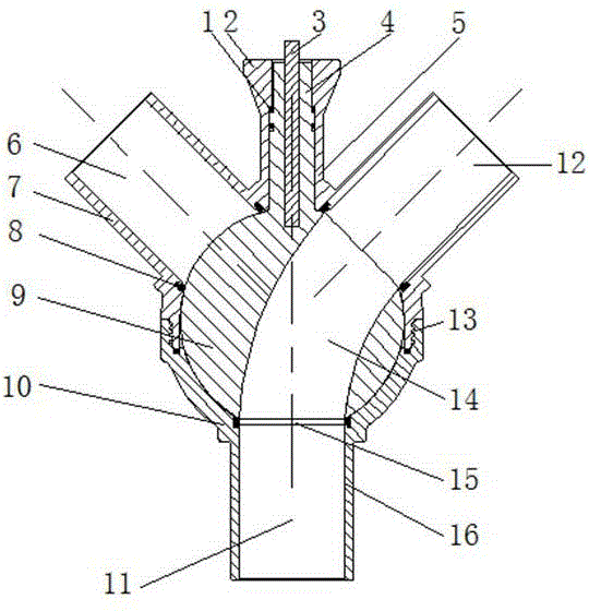
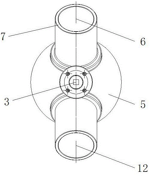
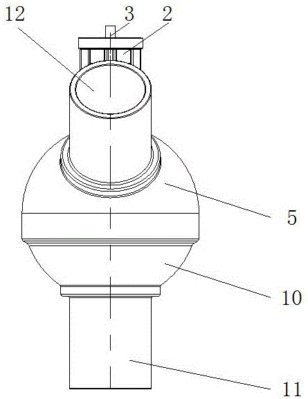
[0015] see Figure 1-3 , an embodiment provided by the present invention: a directional control valve, including a casing 5 and a pipe wall 7, a directional control pipe 2 is arranged on the casing 5, and an O-shaped seal is arranged between the directional control pipe 2 and the cylinder 4 The ring 1, the control rod 3 is arranged in the direction control pipe 2, the pipe A6 is arranged on one side of the casing 5, and the pipe C12 is connected to the other s...


PUM


Abstract

The invention discloses a direction control valve used for being connected with three or more single pipes or pipelines intersecting with pipes or pipelines. The direction control valve comprises a shell. The shell is provided with a spherical inner cavity. The shell is provided with at least two pipelines communicating with the spherical inner cavity. A spherical valve element is arranged in the spherical inner cavity. A control column extending out of the surface of the shell is arranged on the outer surface of the spherical valve element. A through hole is formed in the spherical valve element, the through hole in the spherical valve element is controlled by the control column to be connected or disconnected with at least two pipelines, and one or more inflow or outflow on-off pipelines are formed. The pipeline A or the pipeline C is selected to be used through a control rod, and the efficiency of a treatment device is improved.

Description

technical field [0001] The invention relates to a valve device, in particular to a directional control valve. Background technique [0002] Various valve configurations and arrangements are known for controlling the flow of gas, liquid or mud in connection with piping systems and pipelines. In some applications it is desirable to be able to provide selective fluid communication between one and more of the various pipes intersecting the main pipe, either by providing each of the individual pipes with its own isolation valve, or by This is accomplished by installing a diverter or "Y" valve in communication with the main feed pipe, although the arrangement described above is very commonly used to allow selection of the direction of fluid flow, due to a hostile liquid environment or obstructions preventing the liquid from passing through the pipe due to gravity Internal flows often present complications. Contents of the invention [0003] The object of the present invention ...

Claims


Application Information

Patent Timeline
Patent Type & Authority Applications(China)
IPC IPC(8): F16K11/087F16K27/06
CPCF16K11/0873F16K27/067
Inventor 张鑫曾捷麦克·格林
Owner 张鑫
Why Eureka
Try Eureka