
Pipeline penetration structure

A technology for penetrating cabins and pipelines, which is applied in the direction of pipes, pipes/pipe joints/fittings, mechanical equipment, etc. It can solve problems such as shortening the service life of the pipeline system, damage to pipeline system components, and affecting the normal operation of equipment, etc., to achieve Improve safety and reliability, protect pipeline structure, and compact structure

Inactive Publication Date: 2017-02-22
NO 719 RES INST CHINA SHIPBUILDING IND
View PDF7 Cites 9 Cited by
  • Summary
  • Abstract
  • Description
  • Claims
  • Application Information

AI Technical Summary

Problems solved by technology

The existing penetrating structure usually uses welding to rigidly connect the outer wall of the pipeline and the bulkhead. However, under the excitation of fluid flow in the pipeline, air compressors, water pumps and other rotating machinery, the pipeline will vibrate. And generate noise, pipeline vibration will cause damage to parts in the pipeline system, shorten the service life of the pipeline system, and affect the normal operation of various equipment. At the same time, the noise generated by pipeline vibration will cause noise pollution and cause adverse effects on the human body

Method used


Image

  • Pipeline penetration structure
  • Pipeline penetration structure

Examples


Embodiment Construction

[0026] The present invention will be further described in detail below in conjunction with the accompanying drawings and specific embodiments.

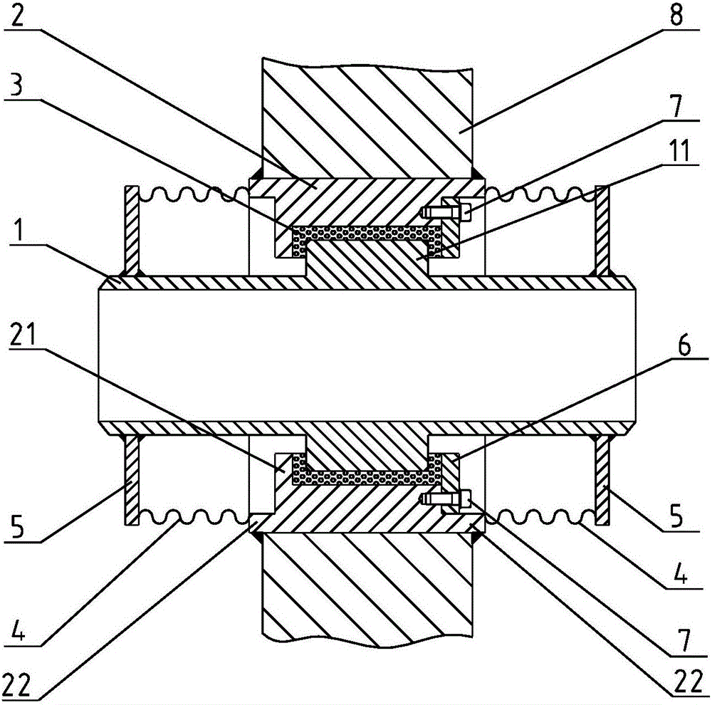
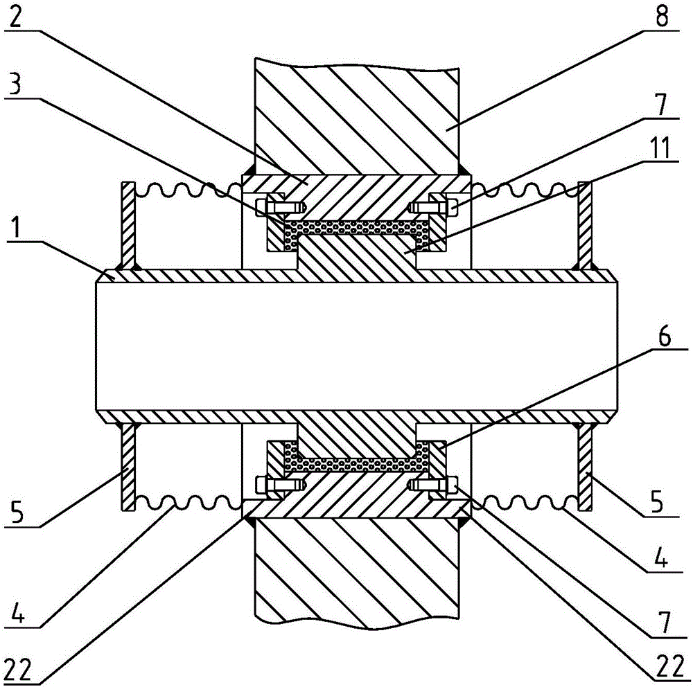
[0027] see figure 1 and figure 2 As shown, the embodiment of the present invention provides a pipeline piercing structure, which includes a transition pipe 1 , a casing 2 , two bellows 4 and a ring plate 5 .

[0028] The casing 2 is sheathed on the transition pipe 1, and an accommodating chamber 3 is formed between the transition pipe 1 and the casing 2, and the accommodating chamber 3 is filled with a damping material. The damping material is metal damping wire or rubber material, and other materials with damping properties can also be used.

[0029] The accommodation cavity 3 is a ring with a "冖" shaped cross section.

[0030] see figure 1 As shown, an embodiment of the present invention is: a protruding annular portion 11 is provided in the middle of the transition pipe 1, a protruding portion 21 extending toward the transitio...


PUM


Abstract

The invention discloses a pipeline penetration structure and relates to the field of pipeline vibration reduction. The system comprises a transition pipe and two corrugated pipes, wherein a sleeve is arranged on the transition pipe in a sleeving manner, and a containing chamber is formed between the transition pipe and the corrugated pipes and is filled with damping materials; the two corrugated pipes are respectively arranged on two sides of the sleeve and respectively arranged at two ends of the transition pipe in a sleeving manner; one end, which is close to the sleeve, of each of the corrugated pipes is connected with the sleeve; an annular plate is arranged on an end face, which is far away from the sleeve, of each of the corrugated pipes; meanwhile, the transition pipe, the sleeve, the corrugated pipes and the annular plate form a sealed area together in a surrounding manner, and the containing chamber is formed in the sealed area. According to the pipeline penetration structure provided by the invention, a cabin space can be effectively sealed, leakage of hazardous substances in the cabin is avoided, the other corrugated pipe can achieve a sealing effect when one corrugated pipe is damaged, and the sealing safety and reliability of the cabin are greatly improved. In addition, the corrugated pipes have buffering and damping effects, and metal corrugated pipes are particularly applied to special application fields at a high cabin temperature.

Description

[0001] The invention relates to the field of pipeline vibration reduction, in particular to a pipeline piercing structure. Background technique [0002] Pipeline is an essential part of the ship system, used for the transport of working fluid and energy transfer between the various equipment in the ship system. Due to the scattered layout of the equipment, the pipeline inevitably needs to pass through different cabins of the ship. The special structure used when the pipeline passes through the bulkhead between different cabins is the tank penetration structure. The penetrating structure not only needs to support the pipeline, but also needs to be sealed with the bulkhead in special cases to ensure the tightness between different compartments. The existing penetrating structure usually uses welding to rigidly connect the outer wall of the pipeline and the bulkhead. However, under the excitation of fluid flow in the pipeline, air compressors, water pumps and other rotating machi...

Claims


Application Information

Patent Timeline
IPC IPC(8): F16L5/02F16L5/00
CPCF16L5/02F16L5/00
Inventor 柳勇赵振兴林原胜白凡戴春辉代路肖颀劳星胜
Owner NO 719 RES INST CHINA SHIPBUILDING IND
Learn More