Solar vacuum heat collecting pipe with double expansion joints

A technology of vacuum heat collecting tubes and expansion joints, which is applied in the field of heat collecting tubes of trough solar heat collectors and trough solar concentrators, can solve the problems of large heat absorbing parts, affecting life, and not easy to fix Reduce heat dissipation, improve utilization efficiency, and facilitate installation and fixation

Active Publication Date: 2017-02-22
SOUTHEAST UNIV
4 Cites 0 Cited by

AI-Extracted Technical Summary

Problems solved by technology

In the current internal expansion joint type and external expansion joint type vacuum heat collecting tube, the heat absorbing part of the heat a...

Method used

[0023] The present invention is a heat collecting tube that is reasonably designed, can improve heat collecting efficiency, is convenient for fixing, is sturdy and durable, and is conducive to safe operation. The invention adopts the vacuum heat collecting tube with double expansion j...

Abstract

The invention discloses a solar vacuum heat collecting pipe with double expansion joints. The solar vacuum heat collecting pipe comprises the inner expansion joint, the outer expansion joint, a kovar alloy pipe, a glass pipe, a heat absorbing pipe, a supporting casing pipe, a flange and a degasser. The glass pipe and the kovar alloy pipe are connected in a fusion seal manner. The kovar alloy pipe and the outer expansion joint are connected through welding. The outer expansion joint and the flange are connected through welding. The flange and the inner expansion joint are connected through welding. The inner expansion joint and the supporting casing pipe are connected through welding. The supporting casing pipe and the heat absorbing pipe are connected through welding. The inner expansion joint and the outer expansion joint are both multi-layer type expansion joints. A fixing bolt hole and a sealing groove are formed in the flange. A vacuum heat collecting pipe body and a tracking device are fixed through the flange. The degasser is located in the kovar alloy pipe located at the end portion. The heat collecting pipe is reasonable in design, capable of improving the heat collecting efficiency, convenient to fix, firm, durable and capable of more safely running.

Application Domain

Technology Topic

Image

  • Solar vacuum heat collecting pipe with double expansion joints
  • Solar vacuum heat collecting pipe with double expansion joints
  • Solar vacuum heat collecting pipe with double expansion joints

Examples

  • Experimental program(1)

Example Embodiment

[0020] The present invention will be further explained below in conjunction with the drawings.
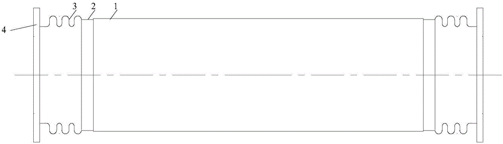
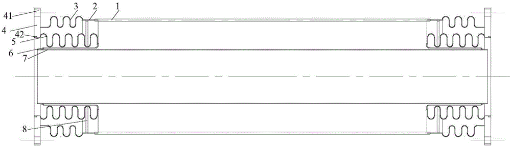
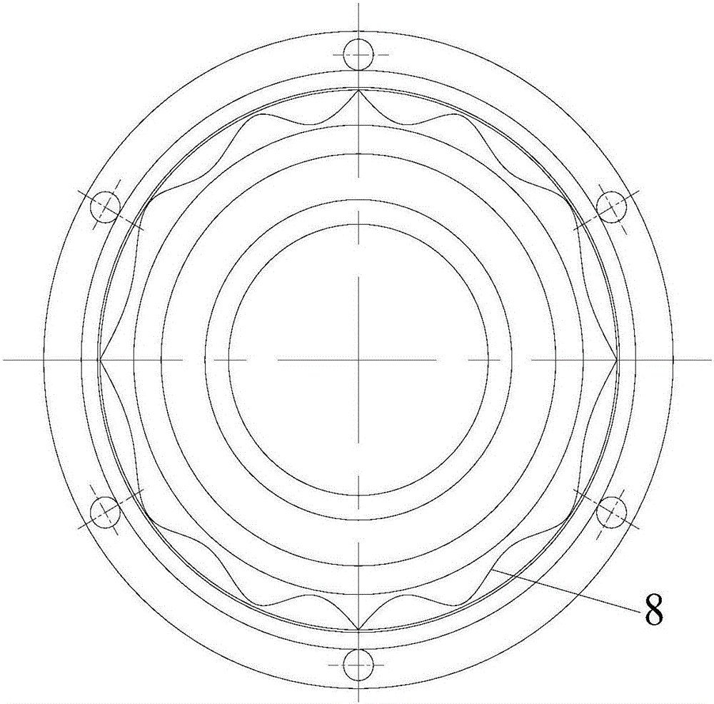
[0021] Such as figure 1 , 2 , 3 and 4 show a trough-type double expansion joint vacuum heat collector tube, including glass tube 1, Kovar alloy tube 2, outer expansion joint 3, flange 4, inner expansion joint 5, support sleeve 6, suction tube Heat pipe 7, getter 8; the glass tube 1 and the Kovar alloy tube 2 are connected by welding, the Kovar alloy tube 2 and the outer expansion joint 3 are connected by welding, and the outer expansion joint 3 and flange 4 are connected by welding For connection, the flange 4 and the inner expansion joint 5 are connected by welding, the inner expansion joint 5 and the support sleeve 6 are connected by welding, the support sleeve 6 and the heat absorption tube 7 are connected by welding, and the getter 8 is placed in the vacuum tube.
[0022] The heat collection tube adopts an outer expansion joint 3 and an inner expansion joint 5, and both expansion joints are multi-layer expansion joints. The flange 4 has a fixing bolt hole 41 and a sealing groove 42, and the vacuum heat collecting tube and the tracking device are fixed by the flange 4. A vacuum is drawn between the glass tube 1 and the heat-absorbing tube 7, and the getter 8 is placed in the space, and is located in the Kovar tube 2 or the outer expansion joint 3 at the end, so that the sunlight will not be affected.
[0023] The invention is a heat collection tube with reasonable design, capable of improving heat collection efficiency, convenient fixation, sturdiness and durability, and beneficial to safe operation. The invention adopts the vacuum heat collection tube with double expansion joints, which can facilitate the installation and fixation of the vacuum heat collection tube, reduce the failure rate of the fusion seal between the glass tube and the Kovar alloy tube, can improve the heat collection efficiency, and is beneficial to the safe operation of the heat collection tube.
[0024] It should be noted that for those of ordinary skill in the art, without departing from the principle of the present invention, several improvements and modifications can be made, and these improvements and modifications should also be regarded as the protection scope of the present invention. All the components that are not clear in this embodiment can be implemented with existing technology.

PUM

no PUM

Description & Claims & Application Information

We can also present the details of the Description, Claims and Application information to help users get a comprehensive understanding of the technical details of the patent, such as background art, summary of invention, brief description of drawings, description of embodiments, and other original content. On the other hand, users can also determine the specific scope of protection of the technology through the list of claims; as well as understand the changes in the life cycle of the technology with the presentation of the patent timeline. Login to view more.

Similar technology patents

Luminous cable sign

Owner:STATE GRID CORP OF CHINA +2

Classification and recommendation of technical efficacy words

  • Improve heat absorption efficiency
  • Easy to install and fix

Solar heat collector and seawater desalination system comprising same

InactiveCN105588342AAvoid thermal blind spotsImprove heat absorption efficiencySolar heating energyGeneral water supply conservationSeawaterSolar thermal collector
Owner:山东大学(威海)

Evaporator core

Owner:TONGLING HUIYU IND CO LTD

Stirling heat engine solar heat collector

ActiveCN103629829AUniform temperatureImprove heat absorption efficiencySolar heating energySolar heat devicesAbsorption rateStirling engine
Owner:斯特林威索AB

LED lamp with water-circulating heat dissipation function

ActiveCN105221970AImprove heat absorption efficiencyEven heat absorptionPoint-like light sourceLighting heating/cooling arrangementsHeat sinkEngineering
Owner:JIANGSU TIWIN OPTO ELECTRONICS TECH

Solar thermal collector system and sounding stave thereof

InactiveCN105737408AAvoid thermal blind spotsImprove heat absorption efficiencySolar heating energySolar heat devicesAbsorption capacitySolar thermal collector
Owner:SHANDONG UNIV

LED road lamp

Owner:江门市佳颂贸易有限公司

Portable spherical infrared camera

Owner:ZHONGSHAN ANLING STAR ELECTRONICS TECH
Why Eureka
Try Eureka