Implementation method of automatic gyro drift compensation of two-axis four-frame photoelectric pod

A photoelectric pod and gyro drifting technology, applied in the direction of measuring devices, instruments, etc., can solve the problems of long time consumption, poor compensation accuracy, and cost, and achieve the effect of fast compensation speed and high compensation accuracy

Active Publication Date: 2017-02-22
中航洛阳光电技术有限公司
View PDF4 Cites 18 Cited by
  • Summary
  • Abstract
  • Description
  • Claims
  • Application Information

AI Technical Summary

Problems solved by technology

Manual drift compensation takes a long time, requiring the pod operator to spend precious time on operations, and the compensation accuracy is not good, and the compensation effect is average
In addition, it is ...

Method used


Image

  • Implementation method of automatic gyro drift compensation of two-axis four-frame photoelectric pod
  • Implementation method of automatic gyro drift compensation of two-axis four-frame photoelectric pod

Examples


Embodiment Construction

[0020] Now in conjunction with embodiment, accompanying drawing, the present invention will be further described:

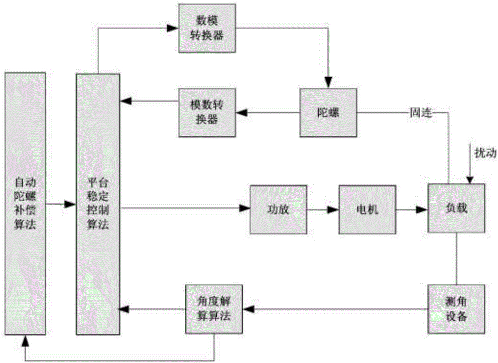
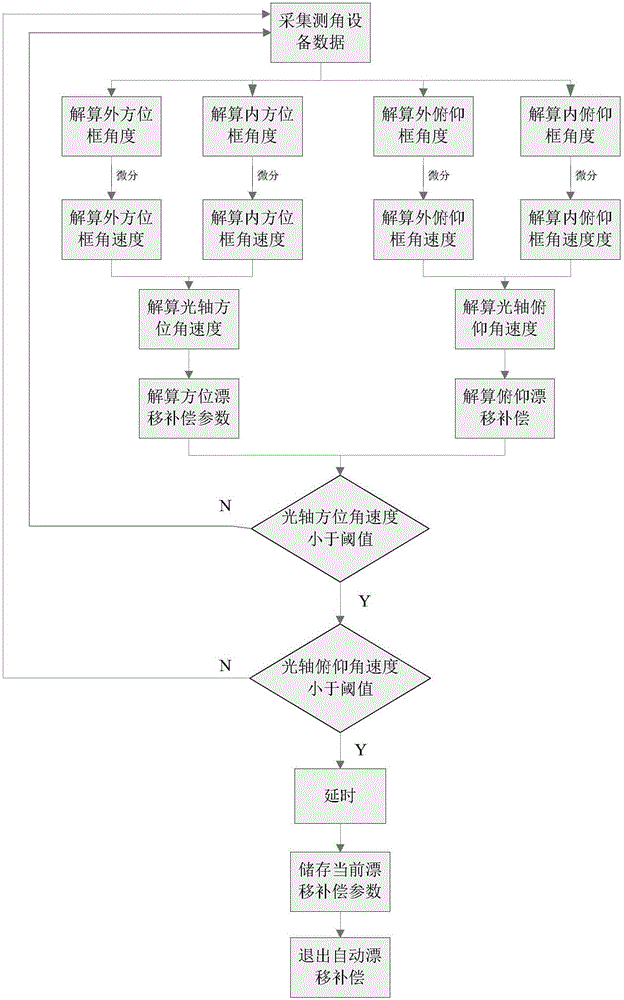
[0021] The two-axis four-frame photoelectric pod has two frames, the outer frame and the inner frame, on each axis of the azimuth and pitch. After the photoelectric pod is started and self-inspected, the pod is kept still. At this time, the angle measuring equipment is continuously collected. The angles of the outer frame and the inner frame on the two axes of azimuth and pitch are calculated by differentially calculating the angular velocity of the outer frame of the pod relative to the pod on the two axis systems.

[0022] Let the angular velocity of the pod relative to the inertial space on a shaft system be ω pod , the angular velocity of the outer frame of the pod relative to the pod is ω o , the angular velocity of the inner frame of the pod relative to the pod is ω i , the angular velocity of the pod optical axis on the corresponding shaft system is ω a...


PUM


Abstract

The invention relates to an implementation method of automatic gyro drift compensation of a two-axis four-frame photoelectric pod for implementing one-key quick automatic gyro drift compensation of the two-axis four-frame photoelectric pod. The implementation method is characterized by comprising the following steps of: starting the pod for self detection, and then keeping the pod standing; at the moment, keeping collection of the angle between an outer frame and an inner frame of the pod and calculating the angular velocities of the outer frame and the inner frame of the pod relative to the pod; resolving the angular velocities of movement of the optical axes according to the angular velocities of the frames, calculating drift compensation parameters according to the angular velocities of the movement of the optical axes to make the optical axes stable in the inertial space, and when the static stability of the optical axes is less than a threshold value, storing the drift compensation parameters and automatically exiting the automatic drift compensation state. The control method for the automatic gyro drift compensation has the advantages that two axis systems of azimuth and pitching of the photoelectric pod can be simultaneously compensated, the compensation speed is fast, the compensation accuracy is high and one-key drift compensation can be realized.

Description

technical field [0001] The invention belongs to the automatic control technology, and relates to a method for realizing automatic gyro drift compensation of a two-axis four-frame photoelectric pod. compensate. Background technique [0002] Due to the physical characteristics of the gyroscope in the photoelectric pod, the gyro drift will occur after the photoelectric pod is powered on. The gyro drift will cause the image of the pod to drift and destroy the stability of the image of the pod, so the pod needs to be drifted. compensate. [0003] Most of the existing pods at home and abroad use the method of manual gyro drift compensation for drift compensation. Manual compensation needs to observe the drift direction of the pod video after the gyro drift of the pod, and set a special drift compensation direction button on the handle of the pod. Operate the buttons, the up and down keys compensate for the drift in the pitch direction, and the left and right keys compensate for ...

Claims


Application Information

Patent Timeline
IPC IPC(8): G01C25/00
CPCG01C25/005
Inventor 张龙浩徐梁杜明昊赵胜斌沈腾
Owner 中航洛阳光电技术有限公司
Why Eureka
Try Eureka