
Weak magnetic flow detector

A magnetic flow and monitor technology, which is applied in the application of electromagnetic flowmeters to detect fluid flow, volume/mass flow generated by electromagnetic effects, and the size/direction of magnetic fields, etc., which can solve the problems of inability to transmit, easily disturbed by noise, and stability No high problems, to achieve strong anti-interference effect

Inactive Publication Date: 2017-02-22
GUANGXI UNIV
View PDF5 Cites 1 Cited by
  • Summary
  • Abstract
  • Description
  • Claims
  • Application Information

AI Technical Summary

Problems solved by technology

[0005] The purpose of the present invention is to provide a weak magnetic flow monitor, so as to overcome the disadvantages that the existing magnetic flow measurement equipment has the characteristics of low stability, is easily disturbed by noise, and the data can only be stored locally and cannot be transmitted.

Method used


Image

  • Weak magnetic flow detector

Examples


Embodiment Construction

[0015] The specific embodiments of the present invention will be described in detail below in conjunction with the accompanying drawings, but it should be understood that the protection scope of the present invention is not limited by the specific embodiments.

[0016] Unless expressly stated otherwise, throughout the specification and claims, the term "comprise" or variations thereof such as "includes" or "includes" and the like will be understood to include the stated elements or constituents, and not Other elements or other components are not excluded.

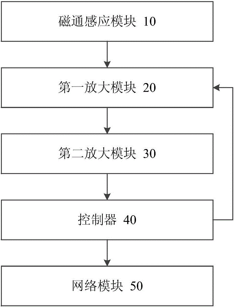
[0017] figure 1 A schematic structural view of a weak magnetic flow monitor according to a preferred embodiment of the present invention is shown.

[0018] Such as figure 1 As shown, the weak magnetic flow monitor includes: a magnetic flux sensing module 10, a first amplifying module 20, a second amplifying module 30, a controller 40 and a network module 50; the magnetic flux sensing module 10 is set in the measured magne...


PUM


Abstract

The invention discloses a weak magnetic flow detector. The detector comprises a flux induction module, a first amplification module, a second amplification module, a controller and a network module, wherein the flux induction module is arranged in a measured magnetic flow environment, and used for converting a magnetic intensity signal into an electric intensity signal; the first amplification module is connected with the flux induction module, and used for stabilizing the voltage value of the electric intensity signal in a fixed amplitude; the second amplification module is connected with the first amplification module, and used for carrying out impedance matching on the electric intensity signal after amplitude is stabilized; the controller is respectively connected with the first amplification module, the second amplification module and the network module; and the controller is used for controlling the voltage stabilizing amplitude of the first amplification module, receiving the electric intensity signal which is subjected to impedance matching by the second amplification module, and transmitting the electric intensity signal to the network module. The method has the advantages of strong interference resistance, long-distance transmission availability and the like since an automatic gain amplifier is introduced to stabilize output signals.

Description

technical field [0001] The invention relates to a weak magnetic flow monitor. Background technique [0002] Magnetic flow measurement works on the principle of electromagnetic induction, transforming magnetism into electricity, and measuring electricity to measure magnetism. [0003] The existing magnetic flow measurement equipment has the characteristics of low stability and is easily disturbed by noise. The data can only be stored locally and cannot be transmitted. [0004] The information disclosed in this Background section is only for enhancing the understanding of the general background of the present invention and should not be taken as an acknowledgment or any form of suggestion that the information constitutes the prior art that is already known to those skilled in the art. Contents of the invention [0005] The purpose of the present invention is to provide a weak magnetic flow monitor, so as to overcome the disadvantages that the existing magnetic flow measurem...

Claims


Application Information

Patent Timeline
IPC IPC(8): G01F1/58G01R33/02
CPCG01F1/58G01R33/02
Inventor 龙邹
Owner GUANGXI UNIV
Learn More