
Remote monitoring and collecting system for electric quantity of building electrical equipment and working method thereof

A remote monitoring and building electrical technology, applied in the measurement of electrical variables, signal transmission systems, measuring devices, etc., can solve the problems of inaccurate power consumption measurement, long time, labor and labor for manual on-site verification, etc., and achieve extended use. Long life, high degree of intelligence, energy saving effect

Inactive Publication Date: 2017-02-22
XUZHOU UNIV OF TECH
View PDF16 Cites 2 Cited by
  • Summary
  • Abstract
  • Description
  • Claims
  • Application Information

AI Technical Summary

Problems solved by technology

[0003] However, human factors and the failure of most electric energy metering systems will lead to inaccurate metering of electricity consumption, resulting in post-event electricity calculation and supplementary work, and even disputes over electricity supplementation
At present, the means of discovering the abnormal information of the user's electric energy metering system mainly relies on manual on-site verification. The manual on-site verification period is at least 3 months. If the time is too long, it will make it difficult to confirm and recover the error power; on-site verification requires the cooperation of the user. And it is difficult to find out the user's subjective breach of contract or electricity theft on the spot; at the same time, manual on-site verification is laborious and laborious

Method used


Image

  • Remote monitoring and collecting system for electric quantity of building electrical equipment and working method thereof
  • Remote monitoring and collecting system for electric quantity of building electrical equipment and working method thereof
  • Remote monitoring and collecting system for electric quantity of building electrical equipment and working method thereof

Examples


Embodiment 1

[0054] Manufacture the casing 1 of the present invention according to the following steps, and in parts by weight:

[0055] Step 1: Add 1400 parts of ultrapure water with a conductivity of 3.28μS / cm into the reactor, start the stirrer in the reactor at a speed of 45rpm, start the heating pump, and raise the temperature in the reactor to 56°C; add in sequence 42 parts of N-isopropylmethacrylamide, 2,3,5,6-tetrafluorobenzyl (1R,3S)-3-(2,2-dichlorovinyl)-2,2-dimethyl 78 parts of cyclopropane carboxylate, 12 parts of 2-(4-morpholinyl) ethyl 2-methyl-2-acrylate, stirred until completely dissolved, adjusted the pH value to 3.5, adjusted the stirrer speed to 124rpm, The temperature was 88°C, and the esterification reaction was carried out for 14 hours;

[0056] Step 2: Take 3-(2,2-dichlorovinyl)-2,2-dimethylcyclopropanoic acid-(1S,3S)-REL-(R)-cyano(3-phenoxyphenyl ) 26 parts of methyl ester, 38 parts of 3-phenoxybenzyl (RS)-3-(2,2-dichlorovinyl)-2,2-dimethylcyclopropane carboxylate...

Embodiment 2

[0061] Manufacture the casing 1 of the present invention according to the following steps, and in parts by weight:

[0062] Step 1: Add 1650 parts of ultrapure water with a conductivity of 6.64μS / cm into the reactor, start the stirrer in the reactor at a speed of 75rpm, start the heating pump, and raise the temperature in the reactor to 84°C; add in sequence 96 parts of N-isopropylmethacrylamide, 2,3,5,6-tetrafluorobenzyl (1R,3S)-3-(2,2-dichlorovinyl)-2,2-dimethyl 126 parts of cyclopropane carboxylate, 56 parts of 2-methyl-2-acrylic acid 2-(4-morpholinyl) ethyl ester, stir until completely dissolved, adjust the pH value to 7.2, adjust the stirrer speed to 224rpm, The temperature is 145°C, and the esterification reaction takes 26 hours;

[0063] Step 2: Take 3-(2,2-dichlorovinyl)-2,2-dimethylcyclopropanoic acid-(1S,3S)-REL-(R)-cyano(3-phenoxyphenyl ) 82 parts of methyl ester, 89 parts of 3-phenoxybenzyl (RS)-3-(2,2-dichlorovinyl)-2,2-dimethylcyclopropane carboxylate were pulv...

Embodiment 3

[0068] Manufacture the casing 1 of the present invention according to the following steps, and in parts by weight:

[0069] Step 1: Add 1520 parts of ultrapure water with a conductivity of 5.12μS / cm into the reactor, start the stirrer in the reactor at a speed of 60rpm, start the heating pump, and raise the temperature in the reactor to 71°C; add in sequence 68 parts of N-isopropylmethacrylamide, 2,3,5,6-tetrafluorobenzyl (1R,3S)-3-(2,2-dichlorovinyl)-2,2-dimethyl 101 parts of cyclopropane carboxylate, 32 parts of 2-methyl-2-acrylic acid 2-(4-morpholinyl) ethyl ester, stir until completely dissolved, adjust the pH value to 5.8, adjust the stirrer speed to 174rpm, The temperature was 118°C, and the esterification reaction was carried out for 20 hours;

[0070] Step 2: Take 3-(2,2-dichlorovinyl)-2,2-dimethylcyclopropanoic acid-(1S,3S)-REL-(R)-cyano(3-phenoxyphenyl ) 56 parts of methyl ester, 63 parts of 3-phenoxybenzyl (RS)-3-(2,2-dichlorovinyl)-2,2-dimethylcyclopropane carbox...


PUM


Abstract

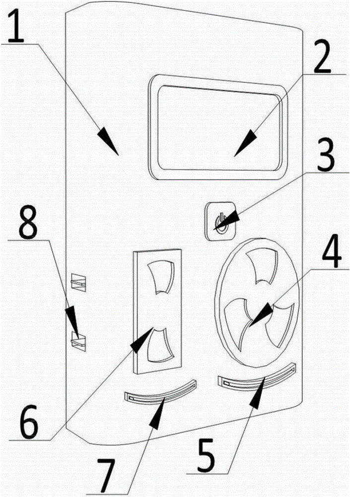
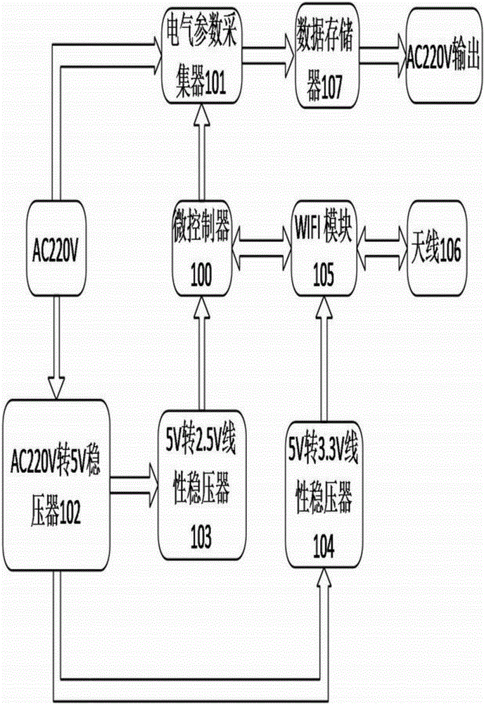
The invention discloses a remote monitoring and collecting system for electric quantity of building electrical equipment and working method thereof. The remote monitoring and collecting system comprises a shell, a data display, a power switch, a three-hole socket, a three-hole keyway, a two-hole socket, a two-hole keyway and a USB interface. The shell is a rectangular structure; the data display is located above the surface of the shell; the power switch is arranged below the data display; the three-hole socket is located below the side surface of the shell, and the three-hole keyway is located below the three-hole socket; the two-hole socket is located below the other side surface of the shell; there are two USB interfaces and the USB interface is arranged on the lower side of the shell; A three-hole insert is provided above the back of the shell. The invention relates to a remote monitoring and collecting system for electric quantity of building electrical equipment, which is highly intelligent and can monitor the electric power consumption of the electric equipment remotely through an electronic equipment terminal in real time and form a data report. The report provides a data base for scientific and reasonable power consumption, which is convenient for energy-saving.

Description

technical field [0001] The invention belongs to the application field of electric quantity monitoring, and in particular relates to a remote monitoring and collecting system for electric quantity of building electrical equipment and a working method thereof. Background technique [0002] In recent years in China, the importance and urgency of strengthening energy-saving monitoring and promoting energy-saving work through information technology has attracted great attention from government departments. Since 2007, a series of energy-saving laws and regulations have been introduced. At the beginning of June 2007, the State Council of China issued the "Comprehensive Work Plan for Energy Conservation and Emission Reduction", which clearly requires the establishment and improvement of the energy conservation and emission reduction index system, monitoring system and assessment system. Energy saving management. In particular, several management opinions were issued for national o...

Claims


Application Information

Patent Timeline
Patent Type & Authority Applications(China)
IPC IPC(8): G01R11/04G01D21/02G08C17/02
CPCG01R11/04G01D21/02G08C17/02
Inventor 陈苏海靳艳辉刘洋
Owner XUZHOU UNIV OF TECH
Learn More