
System and method for detecting fault of DC grounding electrode line

A technology for direct current grounding and line faults, which is applied to fault locations, information technology support systems, and fault detection according to conductor types. Effects of Adaptability, Increased Range, and Reduced Complexity

Active Publication Date: 2017-02-22
NR ELECTRIC CO LTD +1
View PDF5 Cites 13 Cited by
  • Summary
  • Abstract
  • Description
  • Claims
  • Application Information

AI Technical Summary

Problems solved by technology

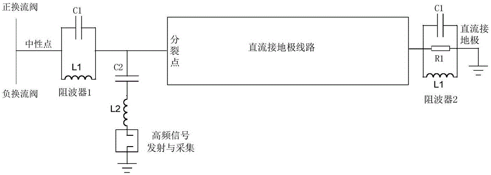
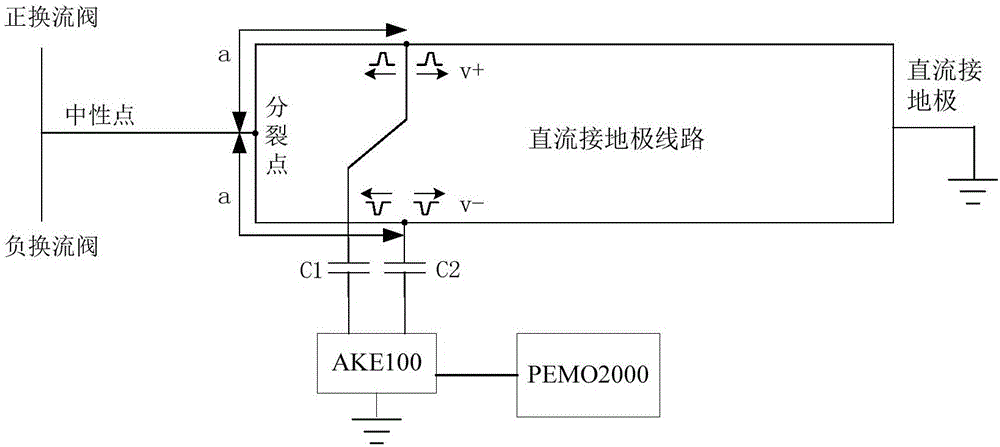
[0008] The purpose of the present invention is to provide a DC grounding electrode line fault detection system and method, through the same set of primary equipment and secondary equipment, the differential mode signal traveling wave method and the common mode signal traveling wave method can be realized at the same time, and the differential mode signal traveling wave method can be solved. The problem that the implementation of the method is limited by the DC site, overcome the problem of low signal amplitude and complex waveform caused by the mutual cancellation of the differential mode signals, and solve the problem that the common mode signal traveling wave method is affected by the directional components and signals of the DC field converter valve, thereby improving Reliability and Distance Measurement Accuracy of DC Grounding Line Fault Detection

Method used


Image

  • System and method for detecting fault of DC grounding electrode line
  • System and method for detecting fault of DC grounding electrode line
  • System and method for detecting fault of DC grounding electrode line

Examples


Embodiment Construction

[0030] Embodiments of the present invention will be further described below in conjunction with the accompanying drawings.

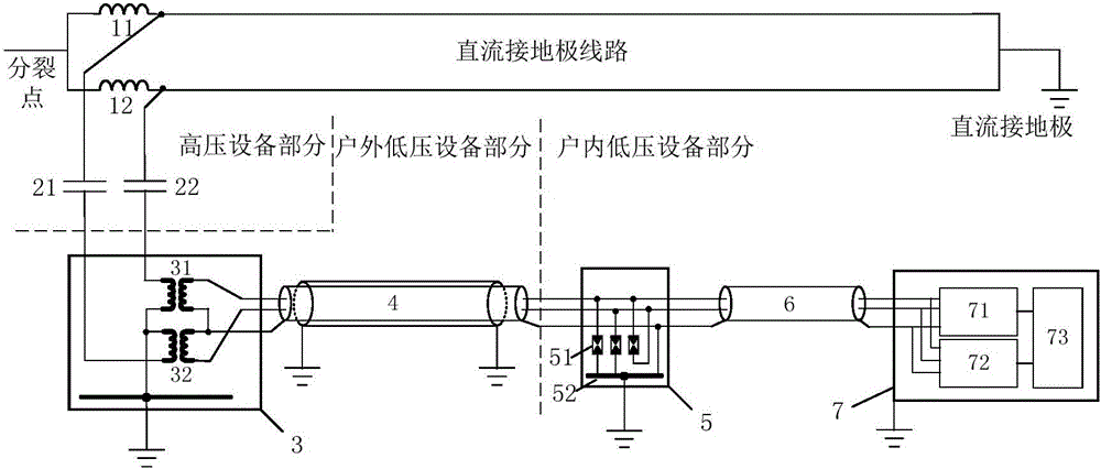
[0031] Such as image 3As shown, a DC grounding electrode line fault detection system and method, the system includes a high-voltage equipment part, an outdoor low-voltage equipment part and an indoor low-voltage equipment part, and the high-voltage equipment part includes high-voltage reactors 11 and 12 arranged on the DC grounding electrode line and high-voltage capacitors 21 and 22, the outdoor low-voltage equipment part includes an impedance matching module 3 and a double-shielded two-core cable 4, and the indoor low-voltage equipment part includes an overvoltage protection module 5, a shielded two-core cable 6 and a fault detection device 7; The high-voltage capacitor is connected to the DC ground electrode line and the impedance matching module through wires, the impedance matching module is connected to the overvoltage protection module through a ...


PUM


Abstract

The invention relates to a system and method for detecting a fault of a DC grounding electrode line, and the system and method achieve the fault discrimination and range finding of the DC grounding electrode line. The system comprises a high-voltage reactor, a high-voltage capacitor, an impedance matching module, an overvoltage protection module, a fault detection device, and a connection cable. The fault detection device can transmit a common mode pulse signal and a differential mode pulse signal, and the common mode pulse signal and the differential mode pulse signal are injected into two conductors of the DC grounding electrode line through the impedance matching module and the high-voltage capacitor. Moreover, a fault reflection traveling wave is detected through the above loop. The high-voltage reactor is disposed at a split part of the grounding electrode line so as to prevent a DC field from affecting a common mode signal traveling wave. The system can reduce the mutual counteracting of differential mode signal traveling waves, and also can enable a differential mode traveling wave method not to be limited by an installation site. The method can improve the amplitude and signal to noise ratio of the traveling wave signals, and can improve the reliability and range finding precision of fault detection of the DC grounding electrode line.

Description

technical field [0001] The invention relates to a DC ground electrode line fault detection system and method, and belongs to the technical field of high-voltage direct current transmission. Background technique [0002] The length of the DC ground electrode line in the DC transmission system may reach tens to more than one hundred kilometers. When the grounding electrode line is short-circuited or open-circuited, it will cause safety hazards to the operation of the DC system. Therefore, it is necessary to perform fault detection on the DC grounding electrode line, including monitoring whether a fault occurs and fault location. Since the DC system operates in balance with the DC unipolar metal return line and the double-pole ground return line, the ground electrode is only used as the potential reference point on the DC side, and no current flows in the DC ground electrode line, and the fault characteristics are not obvious at this time. Not easy to detect. When the DC syst...

Claims


Application Information

Patent Timeline
Patent Type & Authority Applications(China)
IPC IPC(8): G01R31/08
CPCG01R31/083Y04S10/52
Inventor 陈玉林张建锋李响汪涛朱晓彤李海英
Owner NR ELECTRIC CO LTD
Learn More