Optical axis debugging system and method of laser range finder

A laser ranging and debugging system technology, applied in the laser field, can solve problems such as unfavorable debugging, limitations of subjective factors, low work efficiency, etc., and achieve the effect of improving optical axis debugging accuracy, high optical axis debugging accuracy, and protecting safety

Inactive Publication Date: 2017-02-22
HUBEI JIUZHIYANG INFRARED SYST CO LTD
View PDF6 Cites 9 Cited by
  • Summary
  • Abstract
  • Description
  • Claims
  • Application Information

AI Technical Summary

Problems solved by technology

The main disadvantages of this method are: first, the use of manual observation and measurement is limited by subjective factors, and the error is large
Second, it is necessary to manually adjust the aiming mechanism of the rangefinder, which is repeated many times and the work efficiency is low
[0006] The disadvantages of the above-mentioned schemes are: they all use analog light sources to calibrate the optical system, the calibration accuracy is low, the system is complicated, and it is not conducive to debugging

Method used


Image

  • Optical axis debugging system and method of laser range finder

Examples


Embodiment Construction

[0038] The present invention will be described in further detail below in conjunction with the accompanying drawings and embodiments.

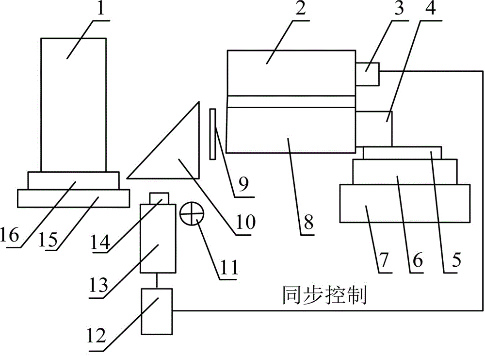
[0039] refer to figure 1 As shown, the present invention discloses a laser distance measuring machine optical axis debugging system, comprising a laser 3, an illumination light source 11 and a CCD camera 13 with a CCD lens 14, the front of the laser 3 is connected with an emission optical system 2, the A computer 12 is connected between the CCD camera 13 and the laser 3, a receiving optical system 8 is arranged in parallel below the emitting optical system 2, and a detector assembly 4 is connected behind the receiving optical system 8, and the receiving optical system 8 is connected with a detector assembly 4. The front of the system 8 is provided with an attenuation sheet 9, a right-angle prism 10 and a corner cube 1 successively, and the right-angle prism 10 can deflect light beams by 90 degrees, wherein the corner cube 1 is positioned at th...


PUM


Abstract

The invention discloses an optical axis debugging system of a laser range finder. The optical axis debugging system comprises a laser, an illumination light source and a CCD camera with a CCD lens, wherein the laser is connected with an emission optical system, and a computer is connected between the CCD camera and the laser. The optical system is connected with the receiving optical system, and the receiving optical system is connected with a detector module, and an attenuating film, a right angle prism and a corner cube prism are arranged in front of the receiving optical system. The invention also discloses a debugging method. The optical axis debugging system can monitor the sharpness of the target surface of the detector assembly in real time, adjust the position of the detector assembly to the optimal position by the adjusting device, and direct the laser spot to the target surface of the detector assembly for optical axis debugging, so that the system is visual and efficient.

Description

technical field [0001] The invention belongs to the field of laser technology, and relates to a system for adjusting an optical axis by combining a near-infrared camera and a corner cube prism, and an adjustment method, which is applicable to various laser optical axis adjustment systems. Background technique [0002] The laser of the laser range finder emits a laser beam, expands the beam through the optical system, and exits to the measured target. The laser beam irradiates the measured target and produces diffuse reflection. The reflected beam is focused on the photodetector through the receiving optical system, and processed by the circuit. After that, the target distance information is calculated. [0003] The "optical axis" of the laser rangefinder is different from the optical axis of general optical instruments, it actually refers to two axes: the optical axis of the laser emitting optical system and the optical axis of the laser receiving optical system. When desig...

Claims


Application Information

Patent Timeline
Patent Type & Authority Applications(China)
IPC IPC(8): G02B7/18G02B7/00
CPCG02B7/1805G02B7/00
Inventor 席文强王寿增郭良贤高彦伟余龙林承飞孙峰
Owner HUBEI JIUZHIYANG INFRARED SYST CO LTD
Why Eureka
Try Eureka