
A low-cost miniature projection system based on LEDs and lenses

A micro-projection and lens technology, applied in the field of projectors, can solve the problems of high difficulty in processing and installation, increased power consumption of the system, color deviation, etc. The effect of the effect of astigmatism

Active Publication Date: 2019-02-15
ANHUI NORMAL UNIV
View PDF9 Cites 0 Cited by
  • Summary
  • Abstract
  • Description
  • Claims
  • Application Information

AI Technical Summary

Problems solved by technology

Although no color wheel is used, this solution has the following defects: (1) LD cost is high; (2) LD electro-optical conversion efficiency is low, resulting in increased power consumption of the system; (3) due to the coherence of the laser, the projected display There will be speckle in the image, which will affect the display effect; (4) The laser needs to pass through three dichroic mirrors, and the light energy will be lost on each dichroic mirror. The cost of the dichroic mirror is high, and the incident The incident angle of light is strictly required. In the process of production or transportation, the angle of incident light incident on the dichroic mirror changes due to slight changes in the position of components, which will reduce the illuminance on the projection screen and cause color deviation, and The overall installation is more difficult; (5) The laser is reflected to the DMD by the mirror, adding optical elements; (6) The lens matrix is ​​closely arranged with gradient index lenses with the same geometric parameters and processing accuracy, and each One gradient index lens corresponds to one of the three colors of red, green and blue light. It is required that the three gradient index lenses have exactly the same refractive index. However, considering the dispersion of the material, it is difficult to process a suitable gradient index lens in large quantities. array
Due to the use of many components and high quality requirements for components, this solution has complex optical paths, high processing and installation difficulties, high cost, low utilization of light energy for the entire system, low electro-optic conversion efficiency of the entire system, and There is a lot of stray light in the system, which limits the volume of the system and increases the difficulty of heat dissipation. For projection systems powered by batteries, it will seriously shorten the working time
[0005] Existing projection system solutions have problems such as low utilization of light energy, low electro-optical conversion efficiency, complex structure, many components, large volume, high cost, and difficulty in heat dissipation.

Method used


Image

  • A low-cost miniature projection system based on LEDs and lenses
  • A low-cost miniature projection system based on LEDs and lenses
  • A low-cost miniature projection system based on LEDs and lenses

Examples


Embodiment 1

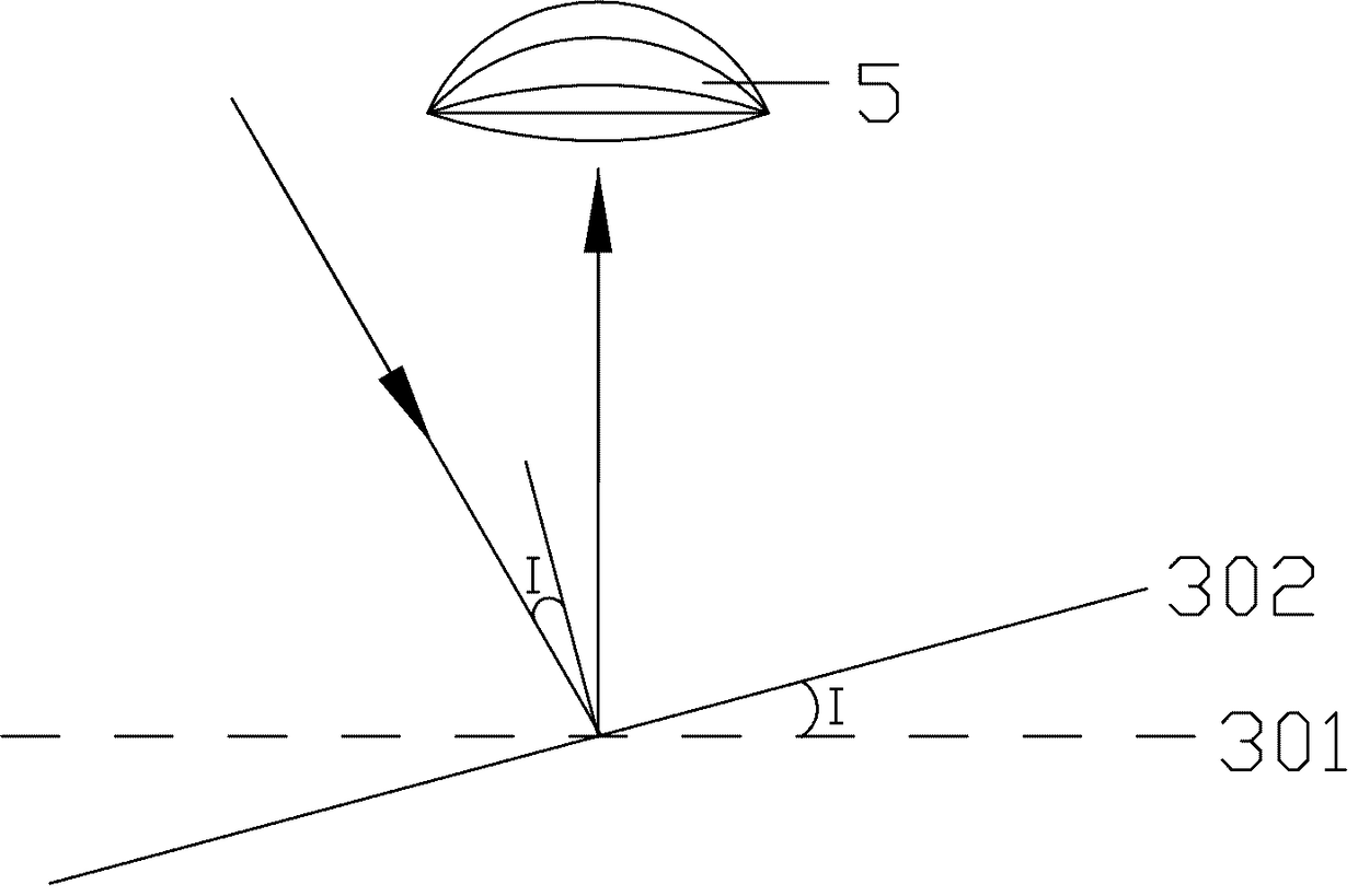
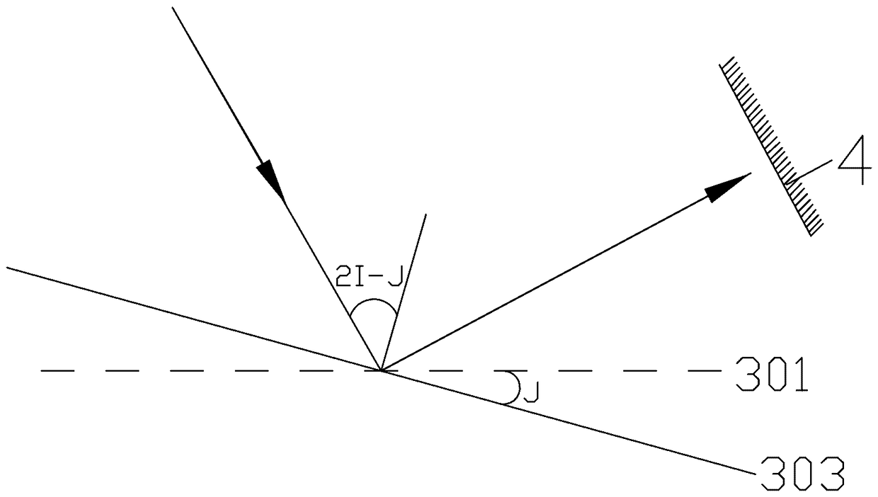
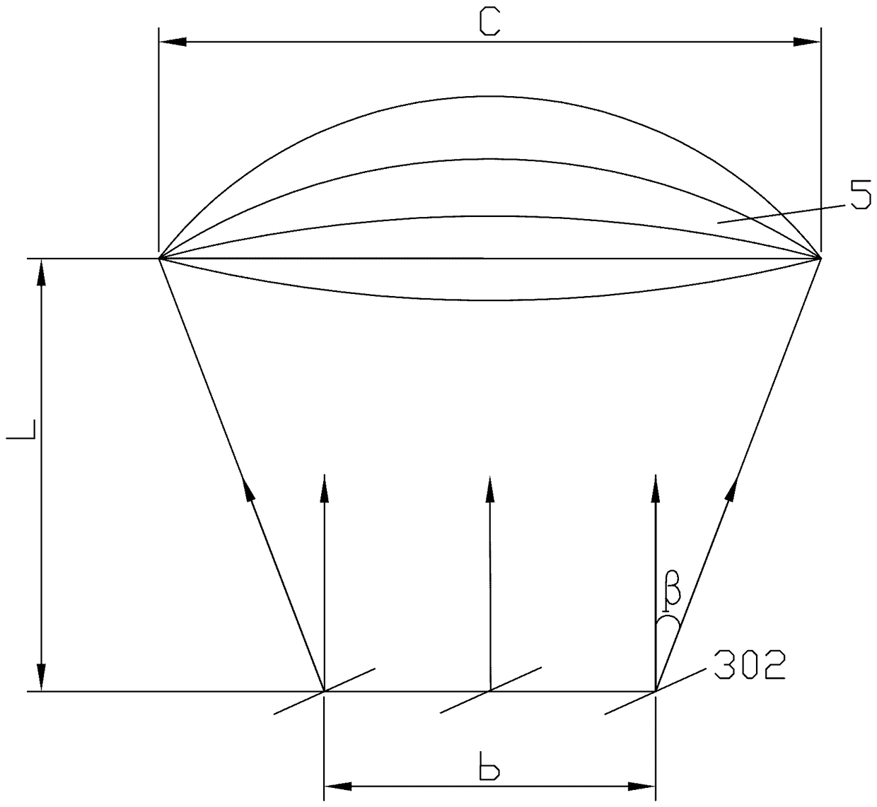
[0054] Embodiment one sees Figure 4 , the optical path of the projection system using LED and convex lens, including LED, convex lens, digital micromirror element, projection lens, absorption device, using convex lens as the shaping lens, the projection system uses a single high-power tri-color LED as the light source, packaged in one LED There are three light-emitting diodes, red, green and blue.

[0055] The single high-power tri-color LED uses the CLMUC-FKA LED lamp bead of Cree Company. The package size of the lamp bead is small, only 1.5mm×1.5mm×1.0mm, and the LED has four pins. The pins that emit red, green, and blue lights are respectively connected to the negative pole, and the remaining common pin is connected to the positive voltage. By controlling the voltage or current of the three pins of red, green, and blue to control the three colors Change; by controlling the strength of the current or the duty cycle, to control the luminous intensity of the three colors.

...


PUM


Abstract

The invention discloses a low-cost miniature projection system based on LEDs and lenses and aims to solve the problems that an existing projection system is low in light energy utilization rate, low in electro-optical conversion efficiency, complex in structure, many in components, large in size, high in cost, difficult in radiating, and the like. The low-cost miniature projection system comprises a light source, a shaping lens, a digital micro-mirror device, a projection lens and an absorption body and is characterized in that the system does not comprise a color wheel, a dichroscope and a light guide tube, and the three-color LEDs replace the role of the color wheel of a traditional projection system in a lighting system. The low-cost miniature projection system has the advantages that the optical structure of the projection system is simplified, the problems of color wheel optical loss, excessively high system temperature and the like of the traditional system are solved, optical energy utilization rate is increased, radiating difficulty is lowered, and the evenness of effective projection area is increased.

Description

technical field [0001] The invention relates to the field of projectors, in particular to a miniature projection system using LEDs and lenses. Background technique [0002] The traditional digital light processing projection system (Digital Light Processing, DLP) is large in size and high in cost; the utilization efficiency of the light source is low, and the uniformity of the projected spot is poor. Its core device is a digital micromirror element (Digital Micromirror) Device,DMD). There are many tiny mirrors on the surface of the digital micromirror element. When the digital micromirror element is not energized, ideally all the mirrors are still in the equilibrium position. This position is called the flat state (flat state). Generally, the micromirrors in the flat state are parallel to the surface of the DMD. After the digital micromirror element is powered on, each mirror can rotate around its own axis. Each mirror has at least two stable working states. In the first s...

Claims


Application Information

Patent Timeline
Patent Type & Authority Patents(China)
IPC IPC(8): G03B21/20
CPCG03B21/2013G03B21/2033G03B21/2066G03B21/208
Inventor 朱向冰钱立勇崔海田朱子辰金慧敏高腾王先盛付贝贝钟婷婷
Owner ANHUI NORMAL UNIV
Learn More