
Method for manufacturing a dimming apparatus

A technology of a display device and a manufacturing method, which is applied in the directions of display devices, illuminated signs, light guides of lighting systems, etc., can solve the problems of cumbersome manufacturing processes and limitations in thinning, and achieves reduction of bonding processes, realization of thinning, The effect of easy thinning

Active Publication Date: 2017-02-22
ALPS ALPINE CO LTD
View PDF11 Cites 0 Cited by
  • Summary
  • Abstract
  • Description
  • Claims
  • Application Information

AI Technical Summary

Problems solved by technology

Therefore, the manufacturing process is cumbersome, and since it becomes a laminated body of films, there is a limit to thinning

Method used


Image

  • Method for manufacturing a dimming apparatus
  • Method for manufacturing a dimming apparatus
  • Method for manufacturing a dimming apparatus

Examples


Embodiment Construction

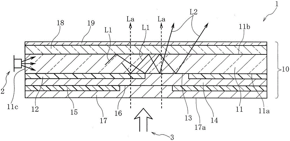
[0054] figure 1 The illumination display device 1 according to the first embodiment of the present invention is shown.

[0055] The illuminating display device 1 has a laminated body 10 , the first light transmitting unit 2 is provided facing the side of the laminated body 10 , and the second light transmitting unit 3 is provided facing the lower side of the laminated body 10 in the drawing.

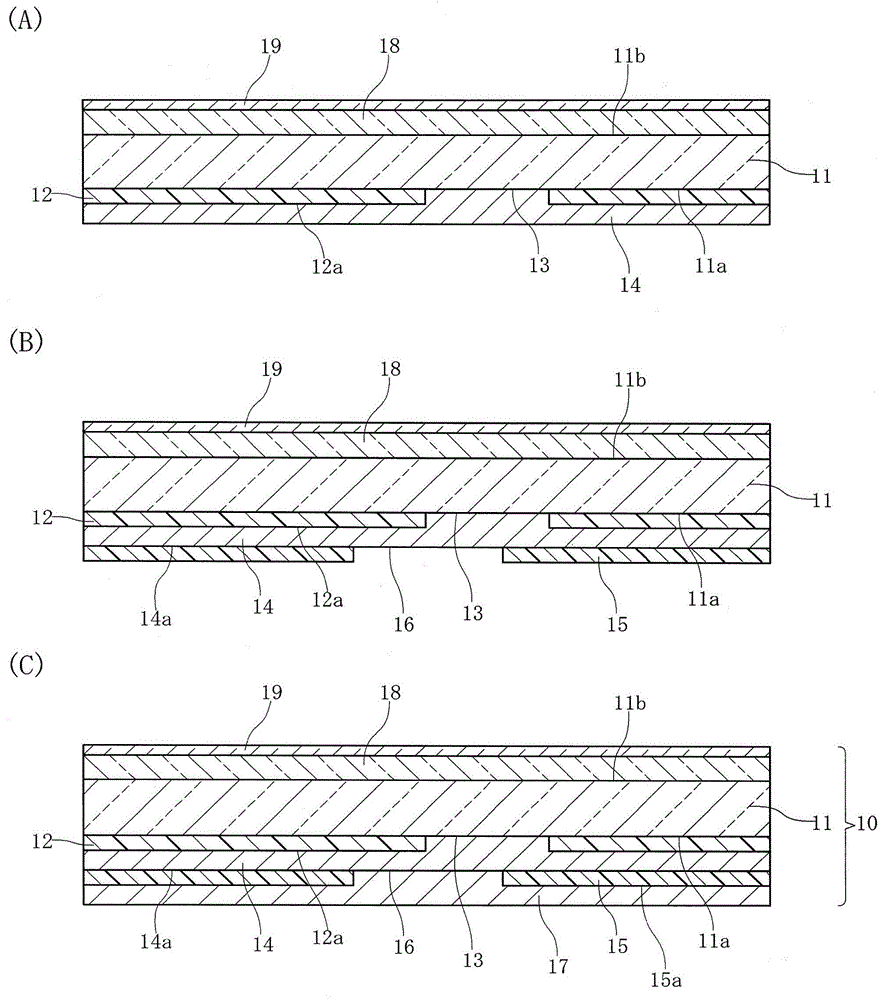
[0056] exist figure 2 (A) (B) (C), the manufacturing process of the laminated body 10 is shown sequentially as a manufacturing method of the illumination display device 1.

[0057] The laminated body 10 has a light guide layer 11 . The light guide layer 11 is formed of a translucent and flexible synthetic resin sheet or synthetic resin plate, such as a polyurethane sheet, polycarbonate sheet, or PET (polyethyleneterephthalic acid) sheet. The plane of the light guide layer 11 facing the lower side in the drawing is the light incident side surface 11 a , and the plane facing the upper...


PUM


Abstract

The invention aims to form a thin illuminating display part through a printing process, the display part switching between a plurality of displays. A low refractive index layer (12), a light scattering layer (14), a light shielding layer (15), and a color filter layer (17) are formed on the surface (11a) on a light incident side of a light guiding layer (11) by a printing process. When a first light sending part (2) is lighted, in a first display pattern (13), light is scattered in the light scattering layer (14) and becomes scattering light (L2), and the first display pattern is displayed through white illumination. Light of a second light sending part (17) passes through the color filter layer (17) and a second display pattern (16), and the second display pattern (16) is illuminated and displayed with color.

Description

technical field [0001] The present invention relates to an illumination display device capable of illuminating by selecting and illuminating a plurality of display patterns including at least one color display, and particularly relates to a method of manufacturing an illumination display device that can be manufactured using a printing process. Background technique [0002] Patent Document 1 and Patent Document 2 describe an illumination display device capable of selecting and illuminating a plurality of display patterns. [0003] In the illuminated display device described in Patent Document 1, ink is applied to the first light guide to form a first low-refractive-index layer in a region other than the first opening, and the surface of the first low-refractive-index layer is and the inside of the first opening to form a scattering layer through a printing process. Then, a mask layer is formed on the surface of the scattering layer except for the second opening. Then, the ...

Claims


Application Information

Patent Timeline
IPC IPC(8): G09F13/18
CPCG09F13/18G09F2013/1831G09F2013/184G09F2013/1863G02B5/223G02B6/0016G02B6/0041G02B6/0065G02B6/0081
Inventor 石田英之伊藤睦夫伊藤直树伊藤彻
Owner ALPS ALPINE CO LTD
Learn More