Organic light emitting display panel and driving method thereof, and organic light emitting display device

A light-emitting display and organic technology, applied in static indicators, instruments, etc., can solve problems such as unstable luminance of organic light-emitting devices, degradation of drive transistor mobility, and failure of pixel drive circuits to increase service life and slow down Decay rate, the effect of guaranteeing the display effect

Active Publication Date: 2017-02-22
WUHAN TIANMA MICRO ELECTRONICS CO LTD +1
View PDF9 Cites 19 Cited by
  • Summary
  • Abstract
  • Description
  • Claims
  • Application Information

AI Technical Summary

Problems solved by technology

The luminescent current of an organic light emitting diode is related to the threshold voltage Vth of the driving transistor, but the threshold voltage Vth of the driving transistor will drift due to the process, aging after long-term use, etc. unstable
Moreover, in the existing pixel drive circuit, the drive transistor works under the bias voltage in the same direction for a long time, which causes the mobility of the drive transistor to decline, resulting in the failure of the pixel drive circuit to work normally.

Method used


Image

  • Organic light emitting display panel and driving method thereof, and organic light emitting display device
  • Organic light emitting display panel and driving method thereof, and organic light emitting display device
  • Organic light emitting display panel and driving method thereof, and organic light emitting display device

Examples


Embodiment Construction

[0020] The application will be further described in detail below in conjunction with the accompanying drawings and embodiments. It should be understood that the specific embodiments described here are only used to explain related inventions, rather than to limit the invention. It should also be noted that, for the convenience of description, only the parts related to the related invention are shown in the drawings.

[0021] It should be noted that, in the case of no conflict, the embodiments in the present application and the features in the embodiments can be combined with each other. The present application will be described in detail below with reference to the accompanying drawings and embodiments.

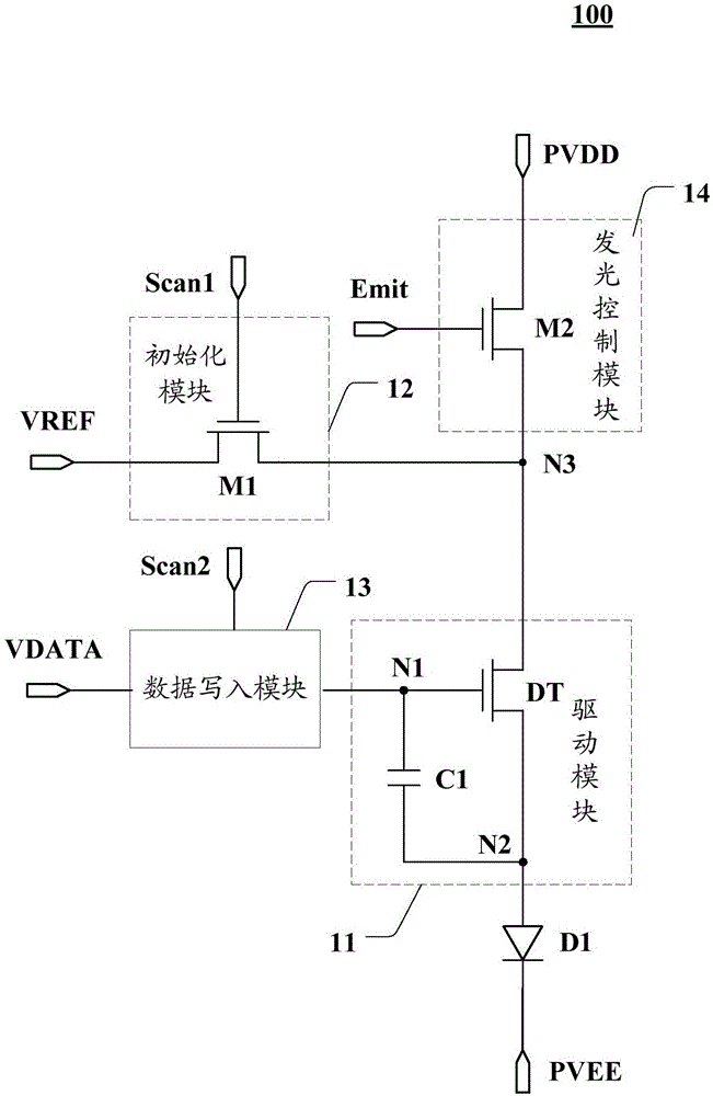
[0022] Please refer to figure 1 , which shows a schematic structural diagram of an embodiment of a pixel driving circuit in an organic light emitting display panel according to the present application. In this embodiment, the organic light emitting display panel includes a ...


PUM


Abstract

The invention discloses an organic light emitting display panel and a driving method thereof, and an organic light emitting display device. The organic light emitting display panel comprises multiple pixel driving circuits which are distributed in an matrix mode, the pixel driving circuits comprise driving modules, initialization modules, data writing modules, light emitting control modules and organic light emitting diodes; the driving modules comprise driver transistors and first capacitances; the initialization modules comprise first transistors, wherein grids of the first transistors, first poles of the first transistors and second poles of the first transistors are electrically connected with first scanning signal ports, initialization signal ports and second poles of driving transistors; the data writing modules are used for transmitting signals in data signal ports to the driving transistors under the control of second scanning signal ports; the light emitting control modules comprise second transistors, and grids of the second transistors, first poles of the second transistors and second poles of the second transistors are electrically connected with light emitting signal ports, first voltage ports and the second poles of the driving transistors respectively. The organic light emitting display panel can effectively delay decay rate of the driving transistors.

Description

technical field [0001] The present application relates to the field of display technology, in particular to an organic light emitting display panel, a driving method thereof, and an organic light emitting display device. Background technique [0002] Organic light-emitting displays use the self-luminous properties of organic semiconductor materials for display, and have the advantages of high contrast and low power consumption. Generally, a pixel array composed of sub-pixels is arranged in a display area of ​​an organic light emitting display. Each sub-pixel contains an organic light-emitting diode, which is driven to emit light by a pixel driver circuit. [0003] A type of existing pixel driving circuit may include a driving transistor, which provides light emitting current to an organic light emitting device under the control of a light emitting control signal. The luminescent current of an organic light emitting diode is related to the threshold voltage Vth of the drivi...

Claims


Application Information

Patent Timeline
Patent Type & Authority Applications(China)
IPC IPC(8): G09G3/3208G09G3/3258G09G3/3266
CPCG09G3/3208G09G3/3258G09G3/3266G09G3/3233G09G2300/0852G09G2300/0861G09G2310/0251G09G2310/0262G09G2320/043G09G2300/0426
Inventor 向东旭李玥吴桐朱仁远刘刚钱栋陈泽源
Owner WUHAN TIANMA MICRO ELECTRONICS CO LTD
Why Eureka
Try Eureka