Insulating paper insertion machine

A technology of insulating paper and inserting machine, applied in laying solid insulation and other directions, can solve the problems of low production efficiency of manual operation, low processing efficiency, damage of insulating paper, etc., achieve linkage interlocking protection and high degree of automation, and meet production and processing needs. , The effect of stable and reliable work

Pending Publication Date: 2017-02-22
NIDE MECHANICAL EQUIP
View PDF8 Cites 11 Cited by
  • Summary
  • Abstract
  • Description
  • Claims
  • Application Information

AI Technical Summary

Problems solved by technology

[0002] The center of the motor stator is a through hole, and there are several grooves on the inner wall of the through hole along the circumferential direction; insulating paper is inserted into each groove, and the insulating paper has good insulation performance, which can greatly improve the working performance of the motor; copper wire According to a certain rule, it is wound on the interval between adjacent slots; the copper wire is insulated from the iron core through the insulating paper, so inserting the insulating paper into the motor stator is a very important processing step, and now the work step of inserting the insulating paper into the stator Either manually, or using equipment such as insulating paper inserting machines, the production efficiency of manual operation is low and cannot meet the production requirements; while the existing insulating paper inserting machines are complicated to operate, cumbersome to debug, and low in processing efficiency , and it is easy to cause damage to the insulating paper, so that the produced motor stator cannot meet the production requirements, which has a negative impact on the actual production and processing

Method used


Image

  • Insulating paper insertion machine
  • Insulating paper insertion machine
  • Insulating paper insertion machine

Examples


Embodiment Construction

[0027] The present invention will be further described in detail below in conjunction with the accompanying drawings and specific embodiments.

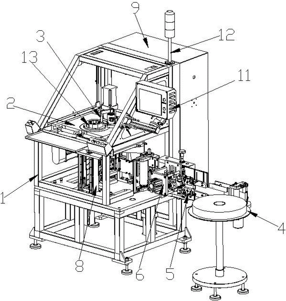
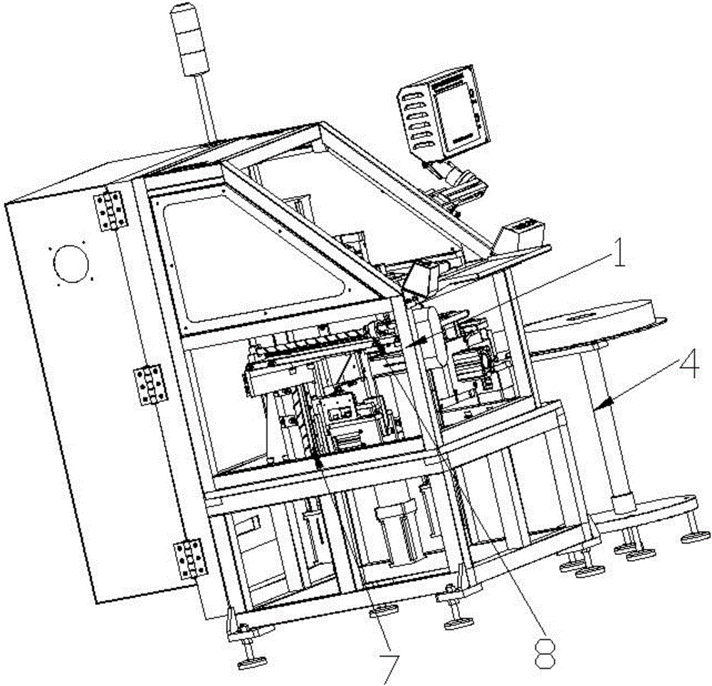
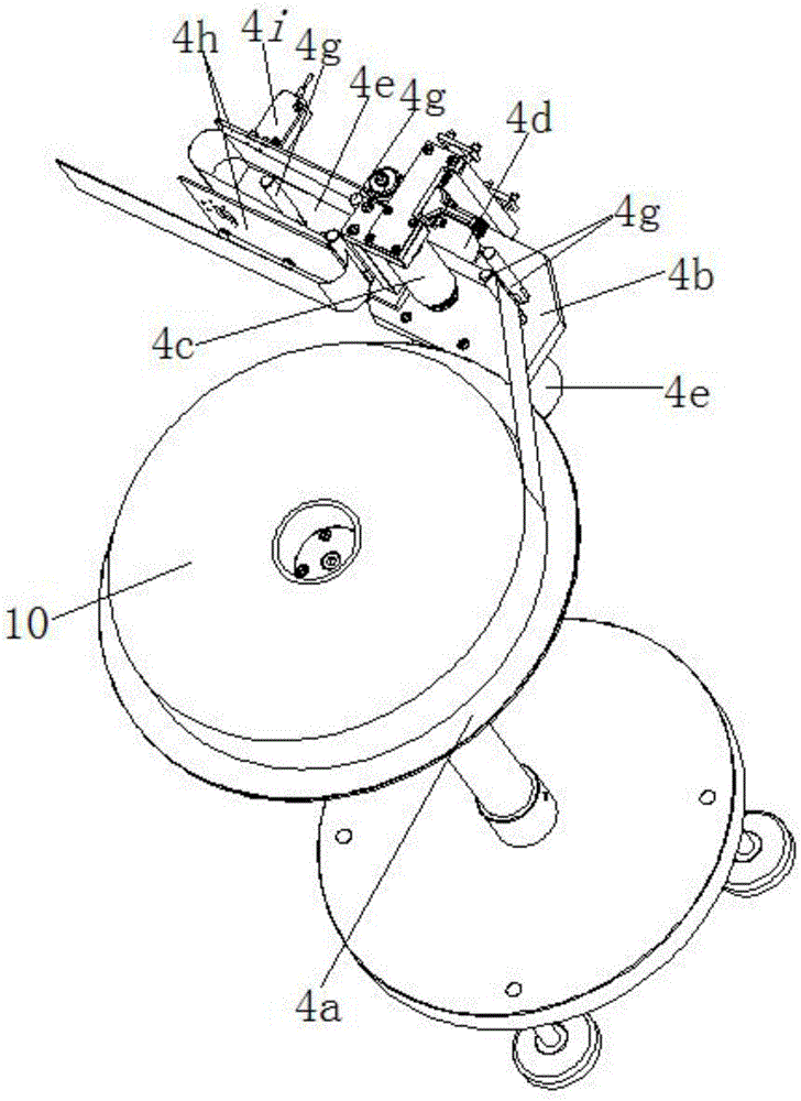
[0028] as attached Figure 1-11 The insulating paper inserting machine shown in the present invention includes a frame 1, a working platform 2 located in the frame 1, an indexing mold device 3, a pre-feeding device 4, a hemming device 5, and a punching conveying device. Device 6, cutting forming device 7 and shifting paper pushing device 8; said working platform 2 is provided with an indexing mold device 3; one side of said frame 1 is provided with a pre-feeding device 4; inside said frame 1 There are sequentially distributed hemming devices 5 and punching conveying devices 6 matched with the pre-feeding device 4; the lower end of the working platform 2 is provided with a cutting forming device 7 matched with the punching conveying device 6; Above the cutting and forming device 7, there is a shifting and pushing paper device 8; after...


PUM


Abstract

The invention relates to an insulating paper insertion machine. A worktable is provided with an indexing die device, a paper pre-feeding device is provided on one side of the rack, and a folding device and a punch transmitting device which are sequentially distributed and matched with the paper pre-feeding device are arranged in the rack. A cutting and forming device matched with the punch transmitting device is arranged at the lower end of the worktable. A paper moving and pushing device is arranged above the cutting and forming device. Insulating paper sequentially passes the folding device, the punch transmitting and the cutting and forming device after being fed by the paper pre-feeding device, and is pushed into a motor stator fixed in the indexing die device through the paper moving and pushing device. The insulating paper insertion machine has the advantages of convenient operation, high processing efficiency, and reliable and stable operation, interlocking protection and high degree of automation, which can meet the actual production and processing needs and have high promotional value, and inserting the insulating paper into the motor stator can be completed automatically.

Description

technical field [0001] The invention relates to a motor stator production equipment, in particular to an insulating paper inserting machine. Background technique [0002] The center of the motor stator is a through hole, and there are several grooves on the inner wall of the through hole along the circumferential direction; insulating paper is inserted into each groove, and the insulating paper has good insulation performance, which can greatly improve the working performance of the motor; copper wire According to a certain rule, it is wound on the interval between adjacent slots; the copper wire is insulated from the iron core through the insulating paper, so inserting the insulating paper into the motor stator is a very important processing step, and now the work step of inserting the insulating paper into the stator Either manually, or using equipment such as insulating paper inserting machines, the production efficiency of manual operation is low and cannot meet the prod...

Claims


Application Information

Patent Timeline
Patent Type & Authority Applications(China)
IPC IPC(8): H02K15/10
CPCH02K15/10
Inventor 熊庆华王健
Owner NIDE MECHANICAL EQUIP
Why Eureka
Try Eureka