Brushless electric machine rotor sheet of automobile brake system

A technology of rotor punching and brushless motors, which is applied in the direction of electric components, electrical components, electromechanical devices, etc., can solve the problems that the main magnetic flux of the motor cannot be further improved, the speed of the weak magnetic field cannot be expanded, and the salient pole effect is not obvious. Achieve the effects of expanding the range of field-weakening speed regulation, reducing the quality, and reducing the harmonic content of the back EMF

Pending Publication Date: 2017-02-22
NIDEC KAIYU AUTO ELECTRIC JIANGSU
View PDF5 Cites 7 Cited by
  • Summary
  • Abstract
  • Description
  • Claims
  • Application Information

AI Technical Summary

Problems solved by technology

The rotor magnets of traditional brushless motors are surface-mounted or embedded, and the main magnetic flux of the motor cannot be further improved. The performance requirements can only be met by increasing the length of the fuselage. Obviously, it is impossible to perform field weakening and speed expansion, and when the motor speed increases, the torque that meets the requirements cannot be output
The relatively high back EMF harmonic content and the relatively high cogging force make the motor torque ripple relatively large. If the rotor is skewed, special tooling is required, resulting in an increase in the cost of the motor

Method used


Image

  • Brushless electric machine rotor sheet of automobile brake system
  • Brushless electric machine rotor sheet of automobile brake system
  • Brushless electric machine rotor sheet of automobile brake system

Examples


Embodiment 1

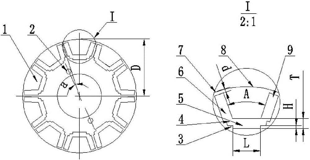
[0022] The punching structure of the present invention is as figure 1 shown.

[0023] The outer circumference of the rotor punch adopts a salient pole structure. The rotor punch has a U-shaped groove 1, and the connection of the U-shaped groove 1 is provided with a magnetic isolation bridge 4 and a positioning step 3. Positioning hole 2.

[0024] The outer circumference of the above-mentioned rotor punch adopts a straight line 7 and an arc 8 to form a salient pole structure. The straight line 7 corresponds to the top formed by two adjacent U-shaped grooves 1. The distance from the top to the straight line 7 is 0.6. When the distance is greater than 0.6, the back EMF harmonic The wave content will rise, and when the distance is less than 0.6, the separation force of the magnetic steel at high speed will damage the mechanical structure of the rotor. The highest point of the arc 8 on the outer circumference of the salient pole corresponds to the center of the U-shaped slot 1. T...


PUM


Abstract

The invention discloses a brushless electric machine rotor sheet of automobile brake system, wherein a peripheral of a rotor sheet utilizes straight lines and arcs to form a salient pole structure. An U-shaped groove is disposed at the rotor sheet. The U-shaped groove is divided into three sections which have the same length. A flux-insulation bridge and a location step are disposed at a joint of the U-shaped groove. The rotor sheet is provided with a location hole for rotor-skewing. A peripheral of the salient pole of the rotor sheet utilizes a structure of straight line and arc, which reduces a content of a counter emf harmonic wave. Optimal designed shape and size of U-shaped magnetic steel groove and the peripheral of the salient pole can expand the range of field-weakening speed expansion of a motor. The motor can provide a certain torque in high speed running and meanwhile magnify the counter emf. A watt density of the motor is improved, and a quality of the motor is reduced. Three sections of the U-shaped groove have the same length, thus the motor only uses one size of magnetic steel, which decreases the cost of the motor. The flux-insulation bridge of the joint of the U-shaped groove also reduces the content of the counter emf harmonic wave. When the rotor is skewing, the skewing location pole is capable of providing a location without a rotor-skewing location frock. The brushless electric machine rotor sheet of automobile brake system is designed properly and is convenient and practical.

Description

technical field [0001] The invention relates to a brushless motor rotor punching plate of an automobile brake system, which belongs to an optimization technology for the brushless motor rotor punching plate of an automobile brake system. Background technique [0002] Automotive brake systems have higher and higher requirements for brushless motors, which require brushless motors to be lightweight, maintain a certain torque output at high speeds, have low torque ripple, and low cost. The rotor magnets of traditional brushless motors are surface-mounted or embedded, and the main magnetic flux of the motor cannot be further improved. The performance requirements can only be met by increasing the length of the fuselage. Obviously, it is impossible to expand the speed of field weakening, and when the motor speed increases, the torque that meets the requirements cannot be output. The relatively high back EMF harmonic content and the relatively high cogging force make the motor to...

Claims


Application Information

Patent Timeline
Patent Type & Authority Applications(China)
IPC IPC(8): H02K29/03H02K1/27
CPCH02K1/276H02K29/03
Inventor 王朝海邱高峰朱金鑫王咏涛
Owner NIDEC KAIYU AUTO ELECTRIC JIANGSU
Why Eureka
Try Eureka