Buck-boost converter and method for controlling buck-boost converter

A technology of step-up and step-down converters, which is applied in the field of circuits, can solve the problems of increased switching loss and reduced efficiency, and achieve the effect of improving efficiency, switching loss and reducing switching loss

Active Publication Date: 2017-02-22
MEDIATEK INC
View PDF8 Cites 5 Cited by
  • Summary
  • Abstract
  • Description
  • Claims
  • Application Information

AI Technical Summary

Problems solved by technology

US Patent No. 6,166,527, US No. 5,402,060 and US No. 7,692,416 disclose some technologies about the step-up buck converter, however, the step-up step-down switching regulator disclosed in the U.S. Patent No. 6,166,527 and the In the boost-buck converter disclosed in US5,402,060, the switch connected to the output voltage cannot conduct both the high voltage and the low voltage (close to 0 voltage or ground voltage), which will reduce the efficiency; while in the U.S. In the up-and-down DC-DC converter disclosed in the patent US7,692,416, the two transistors of the transmission gate (transmission gate) connected to the output voltage are affected by the correlation in the boost mode and the buck mode. Signal control, and switching loss will increase in this operation

Method used


Image

  • Buck-boost converter and method for controlling buck-boost converter
  • Buck-boost converter and method for controlling buck-boost converter
  • Buck-boost converter and method for controlling buck-boost converter

Examples


Embodiment Construction

[0024] Certain terms are used throughout the specification and following claims to refer to particular components. Those skilled in the art should understand that hardware manufacturers may use different names to refer to the same component. This document does not use the difference in name as a way to distinguish components, but uses the difference in function of components as a criterion for distinguishing. In the following description and claims, the terms "comprising" and "comprising" are open-ended terms, so they should be interpreted as "including but not limited to". In addition, the term "coupled" herein includes direct and indirect electrical connection means. Therefore, if a device is coupled to another device, it means that the one device may be directly electrically connected to the other device, or indirectly electrically connected to the other device through other devices or connecting means.

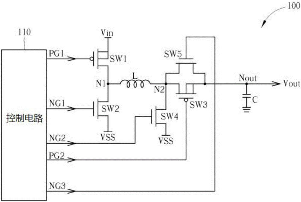
[0025] Please refer to figure 1 , which is a schematic diagram of ...


PUM


Abstract

The invention discloses a buck-boost converter and a method for controllng the same. A buck-boost converter includes an inductor including a first terminal and a second terminal, a first switch, a second switch, a third switch, a fourth switch and a fifth switch, wherein the first switch is coupled between an input voltage and a first terminal of the inductor, the second switch is coupled between a reference voltage and the first terminal of the inductor, the third switch is coupled between an output voltage and a second terminal of the inductor, the fourth switch is coupled between the reference voltage and the second terminal of the inductor, and the fifth switch is connected in parallel with the third switch. When the buck-boost converter operates in a buck mode, the first switch and the second switch are turned on alternately, and the fifth switch is turned on; when the buck-boost converter operates in a boost mode, the third switch and the fourth switch are turned on alternately, and the fifth switch is turned off. The buck-boost converter can improve the efficiency and reduce switch loss.

Description

[0001] This application claims priority to U.S. Provisional Application No. 62 / 202,602, filed August 7, 2015, the entire contents of which are incorporated herein by reference. [0002] 【Technical field】 [0003] The invention relates to the field of circuits, in particular to a step-up and step-down converter and a control method thereof. [0004] 【Background technique】 [0005] When an electronic device receives an input voltage with a wide range, a buck-boost converter is often used in the electronic device to provide a stable output voltage. US Patent No. 6,166,527, US No. 5,402,060 and US No. 7,692,416 disclose some technologies about the step-up buck converter, however, the step-up step-down switching regulator disclosed in the U.S. Patent No. 6,166,527 and the In the boost-buck converter disclosed in US5,402,060, the switch connected to the output voltage cannot conduct both the high voltage and the low voltage (close to 0 voltage or ground voltage), which will reduce t...

Claims


Application Information

Patent Timeline
Patent Type & Authority Applications(China)
IPC IPC(8): H02M3/158
CPCH02M3/1582H02M1/0054H02M3/158Y02B70/10G05F1/62H02M3/1584H02M3/1588
Inventor 洪浩评林诗梅
Owner MEDIATEK INC
Why Eureka
Try Eureka