
QE testing apparatus and testing method for solar cell

A solar cell and test device technology, applied in the field of solar cells, can solve the problems of taking wrong cells to be tested, difficulty in testing work, and very limited adjustments, so as to improve test efficiency and work efficiency, and the test method is simple and easy to implement. The effect of improving test efficiency

Active Publication Date: 2017-02-22
盐城阿特斯阳光能源科技有限公司
View PDF4 Cites 6 Cited by
  • Summary
  • Abstract
  • Description
  • Claims
  • Application Information

AI Technical Summary

Problems solved by technology

Obviously, this adjustment process is very time-consuming and laborious, and it is very prone to inaccurate testing
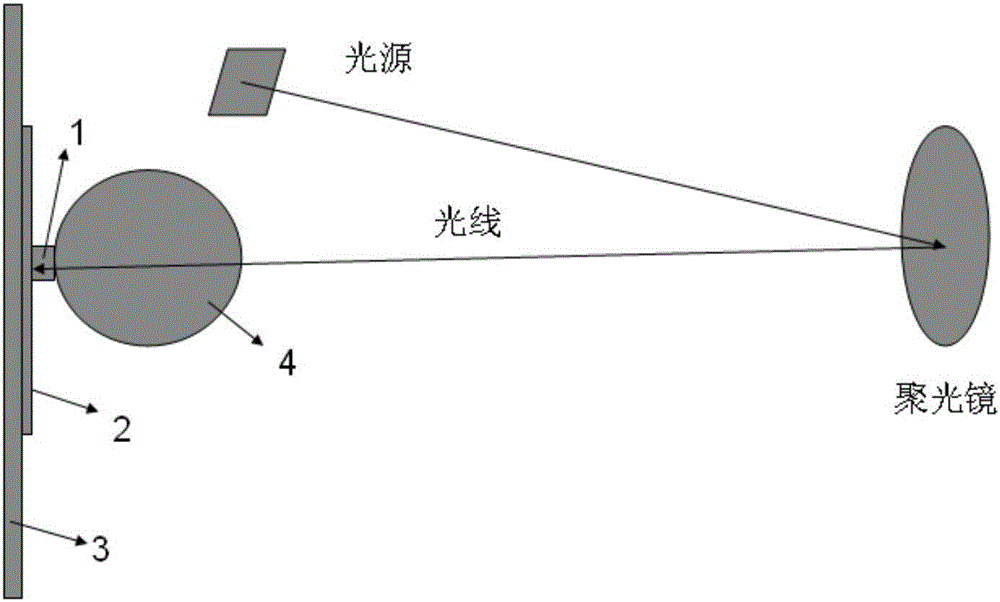
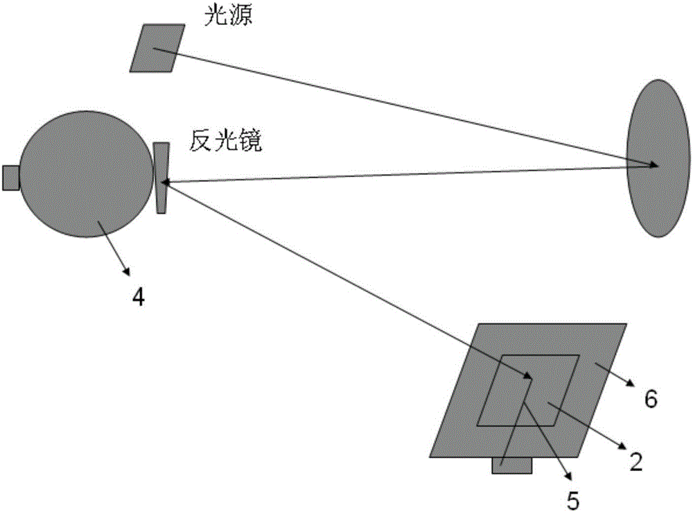
In addition, there will be the following problems in the actual test process: (1) Since the test is generally repeated many times, it is necessary to prepare multiple pieces of cells to be tested. If the cell is transferred from one test platform to another, it is very easy to take the wrong cell to be tested, or it is very easy to have a test item that is not completed and be used by other testers to do other test items, resulting in confusion ; (2) During the QE test, because the light needs to be irradiated to the A area, the adjustment of the optical path is very limited. However, since the probe needs to be pressed on the cell to be tested, the probe and the The corresponding brackets and other mechanisms block the light, which is difficult to achieve when the optical path adjustment is difficult, which brings practical difficulties to the test work

Method used


Image

  • QE testing apparatus and testing method for solar cell
  • QE testing apparatus and testing method for solar cell
  • QE testing apparatus and testing method for solar cell

Examples


Embodiment 1

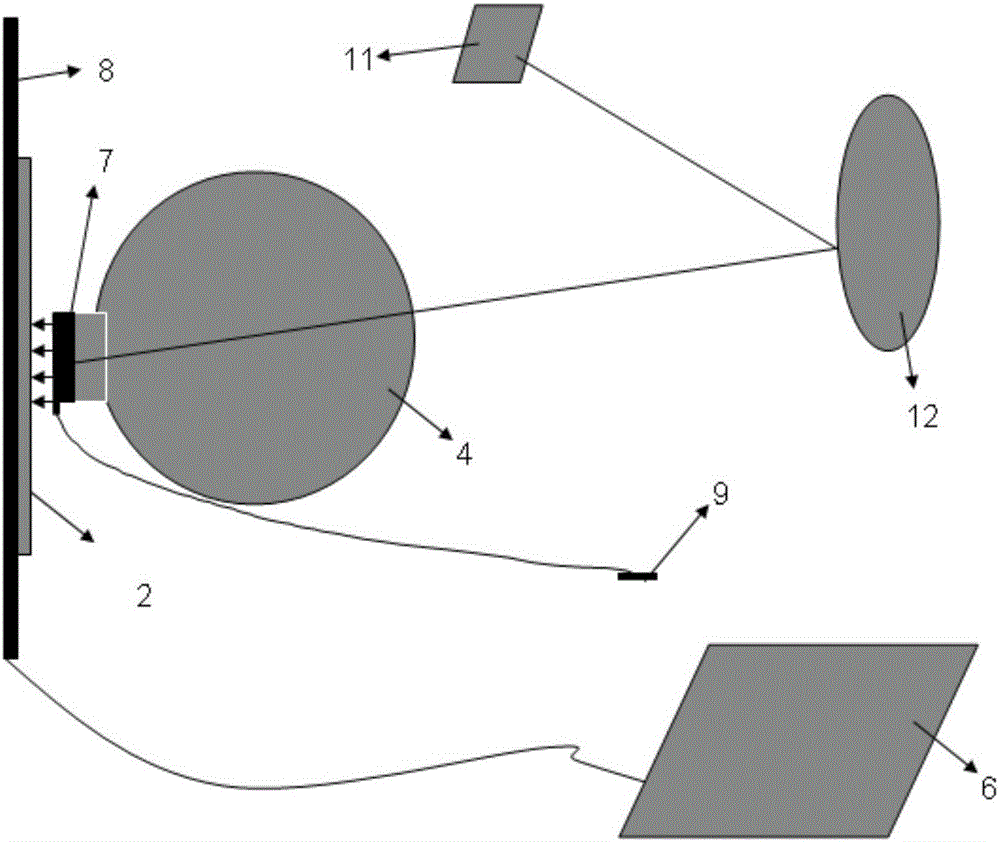
[0041] see Figure 3~6 Shown, a kind of QE testing device for solar cell is mainly made up of light source 11, condenser mirror 12, integrating sphere 4, probe and QE testing platform 6; Described integrating sphere has integrating sphere light outlet;

[0042] The probe is an arc-shaped probe row 7, and the central angle corresponding to the arc is 350 degrees;

[0043] The probe row and the light outlet of the integrating sphere form a detachable connection structure, and when the probe row is installed on the light outlet of the integrating sphere, the circle where the arc-shaped probe row is located and the circle where the light outlet of the integrating sphere is located coincide,

[0044] The probe row includes a probe bracket 10 and a plurality of probes arranged on the probe bracket, and when the probe row is installed on the light outlet of the integrating sphere, the probes have the ability to move up and down relative to the light outlet of the integrating sphere....


PUM


Abstract

The invention discloses a quantum efficiency (QE) testing apparatus for a solar cell. The apparatus is composed of a light source, a collecting lens, an integrating sphere, a probe and a QE test platform. The integrating sphere has an integrating sphere light outlet. The probe is an arc probe bar, wherein the central angle corresponding to the arc is smaller than 360 degrees. When the probe bar is installed at the integrating sphere light outlet, light from the integrating sphere light outlet is located inside the arc probe bar in an encircling manner. And the circle where the arc probe bar is located is overlaid with the circle where the integrating sphere light outlet is located; or the diameter difference of the two circles is smaller than 5mm and the distance of the centers of the two circles is smaller than 5mm. Using the testing apparatus provided by the invention, reflectivity and QE / IQE testing can be completed during the whole course after the one-off loading operation, so that the testing efficiency and the working efficiency are improved substantially.

Description

technical field [0001] The invention relates to a QE test device and a test method for solar cells, belonging to the technical field of solar cells. Background technique [0002] Conventional fossil fuels are being exhausted day by day. Among the existing sustainable energy sources, solar energy is undoubtedly the cleanest, most common and most potential alternative energy source. Solar power generation devices, also known as solar cells or photovoltaic cells, can directly convert solar energy into electrical energy. The principle of power generation is based on the photovoltaic effect of semiconductor PN junctions. [0003] Comprehensive analysis of the parameter information of solar cells is becoming more and more important to improve the overall efficiency of photovoltaic power generation systems. Comprehensive measurement of the quantum efficiency (QE) of solar cells is an important way to obtain the above parameters. In the prior art, a QE testing device is generally u...

Claims


Application Information

Patent Timeline
Patent Type & Authority Applications(China)
IPC IPC(8): H02S50/15
CPCH02S50/15Y02E10/50
Inventor 李琰琪万松博王栩生邢国强
Owner 盐城阿特斯阳光能源科技有限公司
Learn More