
PCB fixing device

A PCB board and fixing device technology, which is applied in the installation board safety device, support structure installation and other directions, can solve the problems of affecting the reliability of the welding of components on the PCB board, reducing the flatness of the metal casing, affecting the appearance quality of the product, etc. The effect of appearance quality, small deformation, and increased weight

Inactive Publication Date: 2017-02-22
GUANGDONG OPPO MOBILE TELECOMM CORP LTD
View PDF9 Cites 5 Cited by
  • Summary
  • Abstract
  • Description
  • Claims
  • Application Information

AI Technical Summary

Problems solved by technology

Due to the exposed screws, the flatness of the metal shell is reduced and the appearance quality of the product is affected
Generally, the boss is stamped on the metal shell as the screw connection. During the stamping process, the metal shell will inevitably be deformed, and the PCB board fixed on the metal shell will also be deformed, which will affect the reliability of the soldering of components on the PCB board.

Method used


Image

  • PCB fixing device
  • PCB fixing device
  • PCB fixing device

Examples


Embodiment Construction

[0024] In order to facilitate the understanding of the present invention, the present invention will be described more fully below with reference to the relevant drawings. The preferred embodiments of the present invention are shown in the drawings. However, the present invention can be implemented in many different forms and is not limited to the embodiments described herein. On the contrary, the purpose of providing these embodiments is to make the disclosure of the present invention more thorough and comprehensive.

[0025] It should be noted that when an element is referred to as being "fixed to" another element, it can be directly on the other element or a central element may also exist. When an element is considered to be "connected" to another element, it can be directly connected to the other element or an intermediate element may be present at the same time. The terms "inner", "outer", "left", "right" and similar expressions used herein are for illustrative purposes on...


PUM

PropertyMeasurementUnit
Thicknessaaaaaaaaaa

Abstract

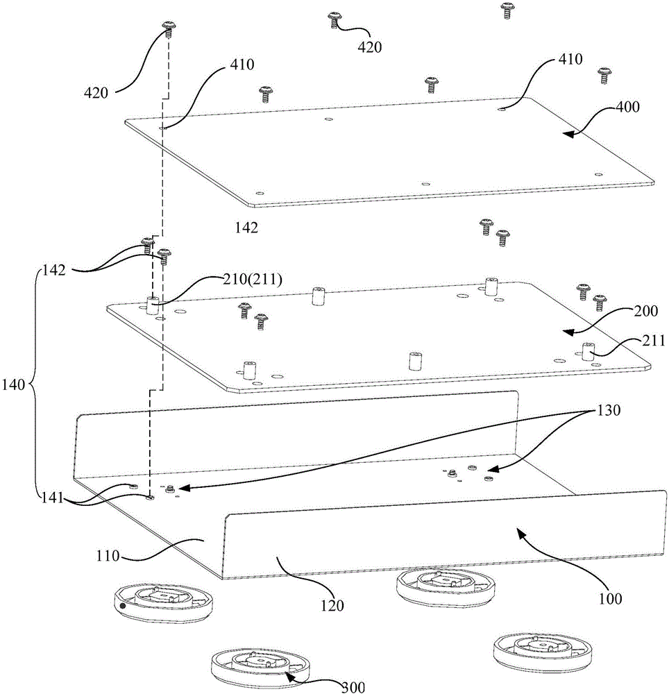
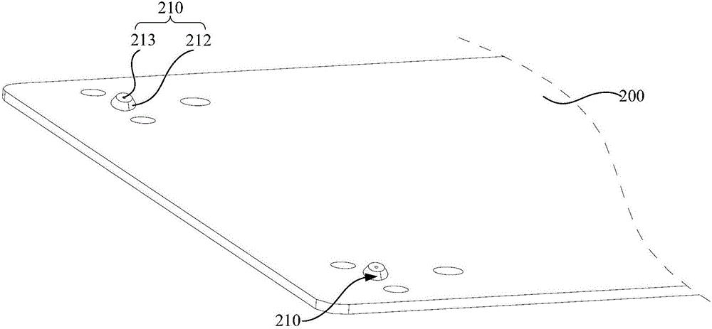
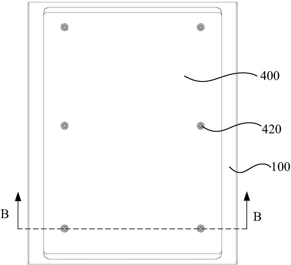
The invention relates to a PCB fixing device used for fixing the PCB. The fixing device comprises a shell body, a support body and a machine leg. The shell body is provided with an installation location and a first connecting piece is arranged in the installation location; the support body is used for installing the PCB and is fixedly connected to the shell body through the first connecting piece; the machine leg is used for supporting the shell body and is arranged in the installation location of the shell body, corresponding to the first connecting piece. A vertical projection of the machine leg on the shell body completely covers a vertical projection of the first connecting piece on the shell body. The PCB is directly installed on the support body and deformation of the support body is small, therefore, the PCB can not be driven to deform and the welding reliability of electronic components on the PCB can be ensured. At the same time, the vertical projection of the machine leg on the shell body completely covers the vertical projection of the first connecting piece on the shell body, the first connecting piece is concealed by the machine leg which is also arranged at the installation location, so that the surface of the shell body is more smooth and the appearance quality of the fixing device is improved.

Description

Technical field [0001] The invention relates to the field of printed circuit boards, in particular to a PCB board fixing device. Background technique [0002] PCB (Printed Circuit Board, printed circuit board) boards are widely used in the technical fields of machinery, electrical and biomedical products. Generally, in some electronic products, the PCB board is directly connected to the metal shell by screws, that is, the screws pass through the shell. Fix the PCB board directly on the metal shell. Because the screws are exposed, the flatness of the metal shell is reduced and the appearance quality of the product is affected. Generally, bosses are stamped on the metal shell as screw connections, and the metal shell will inevitably be deformed during the stamping process, so that the PCB board fixed on the metal shell will also be deformed, which affects the reliability of the soldering of the components on the PCB board. Summary of the invention [0003] Based on this, it is nec...

Claims


Application Information

Patent Timeline
IPC IPC(8): H05K7/14
CPCH05K7/1417
Inventor 陈仕权
Owner GUANGDONG OPPO MOBILE TELECOMM CORP LTD
Learn More