Heat dissipation apparatus and manufacturing method therefor
A heat dissipation device and heat dissipation pipe technology, which is applied in the direction of cooling/ventilation/heating transformation, electrical equipment structural parts, electrical components, etc., can solve the problems of shortened life, affecting heat dissipation effect, and many metal heat conducting fins, etc., to increase contact area, improve the heat dissipation effect, and improve the effect of thermal conductivity
- Summary
- Abstract
- Description
- Claims
- Application Information
AI Technical Summary
Problems solved by technology
Method used
Image

Examples
Embodiment 1
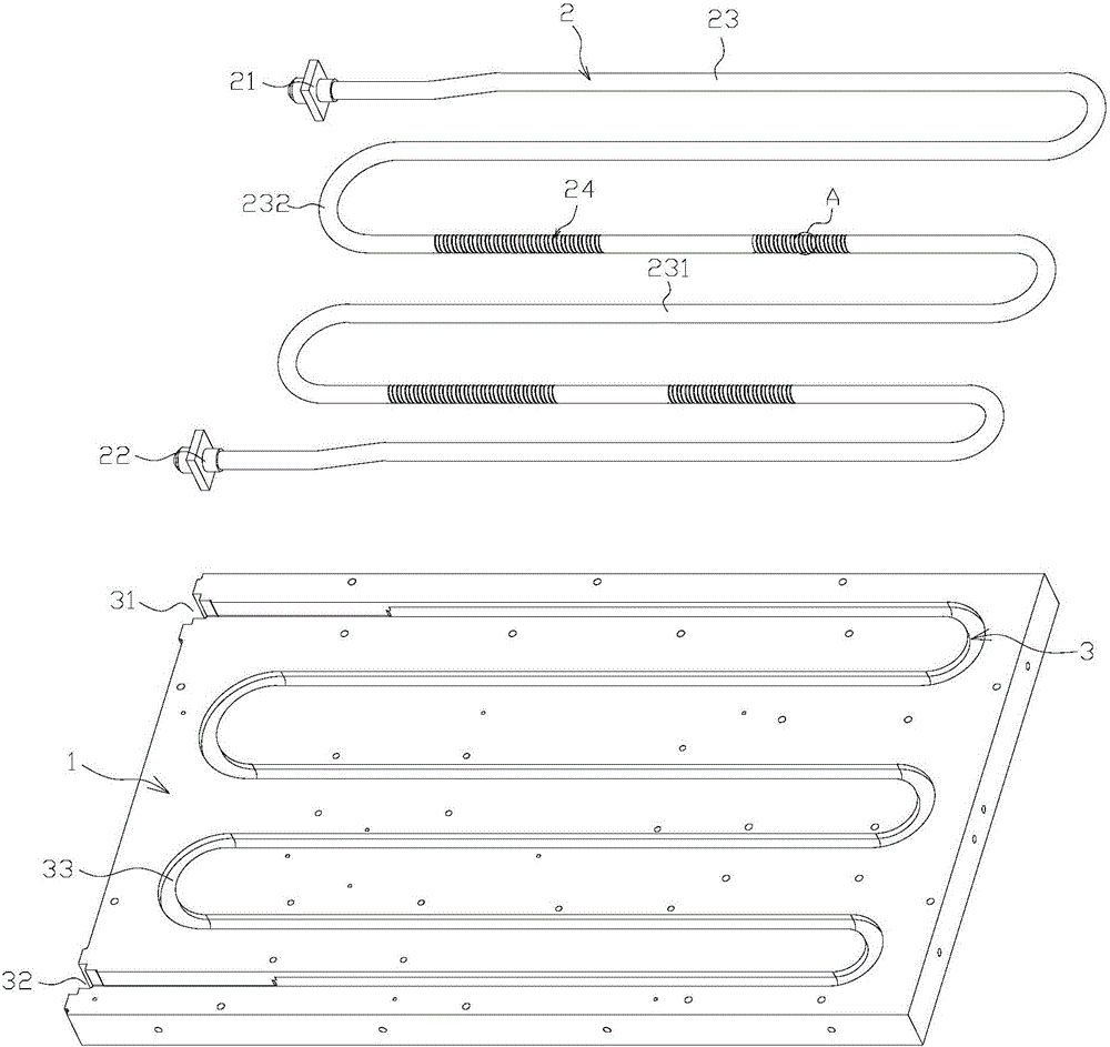
[0026] see Figure 1 to Figure 3 , a heat dissipation device, comprising a heat dissipation plate 1 and a heat dissipation pipe 2, the heat dissipation plate 1 is provided with a tank body 3, and the groove body 3 includes a liquid inlet groove 31 and a liquid outlet groove 32 penetrating through the side of the heat dissipation plate 1, And the heat dissipation groove 33 communicating with the liquid inlet groove 31 and the liquid outlet groove 32, the heat dissipation pipe 2 includes the liquid inlet pipeline 21, the liquid outlet pipeline 22, and the heat dissipation pipeline connecting the liquid inlet pipeline 21 and the liquid outlet pipeline 22 23. The shape of the heat dissipation pipe 2 is designed to match the track of the tank body 3. The liquid inlet pipe 21 is installed in the liquid inlet tank 31 and extends outward to the outside of the heat dissipation plate 1. The The liquid outlet pipe 22 is installed in the liquid outlet groove 32 and extends outward to the ...
Embodiment 3
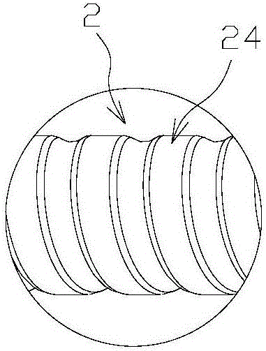
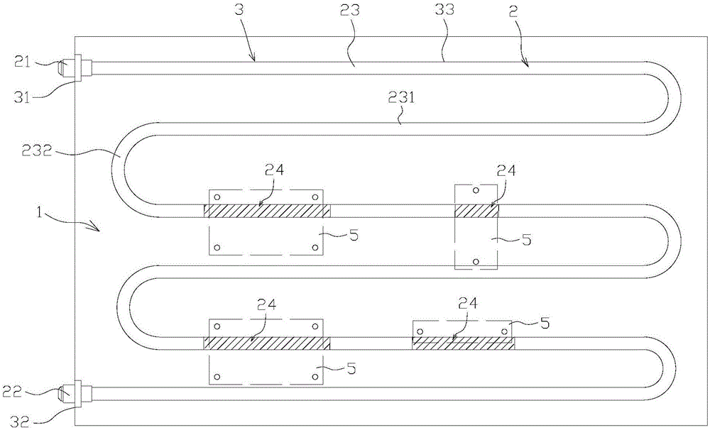
[0039] The difference between this embodiment and Embodiment 1 lies in the difference in the arrangement of the recessed part. The recessed part in this embodiment is an annular recessed part, and a plurality of annular recessed parts are arranged at intervals along the axis of the heat pipe. Preferably Yes, in order to reduce the manufacturing cost, a plurality of continuous ring-shaped depressions form one section, and several sections are intermittently arranged on the heat dissipation pipe. The number of segments is determined according to the position and quantity of the heating elements arranged on the heat dissipation plate, that is, the annular recess is only provided on the heat dissipation pipe located under the heat dissipation element that needs to be cooled, and the distance between the part of the heat dissipation pipe and the tank is increased. The contact area ensures good thermal conductivity. Preferably, the axial length of each annular recess should be greate...
PUM
 Abstract
Description
Claims
Application Information
 - R&D
- Intellectual Property
- Life Sciences
- Materials
- Tech Scout
- Unparalleled Data Quality
- Higher Quality Content
- 60% Fewer Hallucinations
Browse by: Latest US Patents, China's latest patents, Technical Efficacy Thesaurus, Application Domain, Technology Topic, Popular Technical Reports.
© 2025 PatSnap. All rights reserved.Legal|Privacy policy|Modern Slavery Act Transparency Statement|Sitemap|About US| Contact US: help@patsnap.com