Fuel pump and method for operating a fuel pump

A fuel pump and fuel technology, which is applied to fuel injection pumps, components of pumping devices for elastic fluids, fuel injection devices, etc., can solve problems such as damage to volumetric efficiency and function, and achieve compact and save structure and cost. , the effect of saving cost and space

Active Publication Date: 2022-04-05
ROBERT BOSCH GMBH
View PDF5 Cites 0 Cited by
  • Summary
  • Abstract
  • Description
  • Claims
  • Application Information

AI Technical Summary

Problems solved by technology

This can greatly impair the volumetric efficiency and function of the pump until it fails completely

Method used


Image

  • Fuel pump and method for operating a fuel pump
  • Fuel pump and method for operating a fuel pump
  • Fuel pump and method for operating a fuel pump

Examples


Embodiment Construction

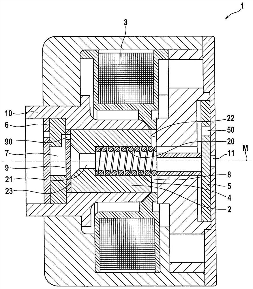
[0023] Refer below figure 1 A fuel pump 1 according to a first preferred embodiment of the present invention will be described in detail.

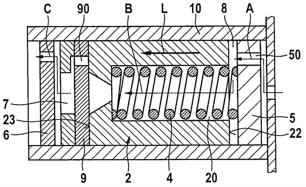
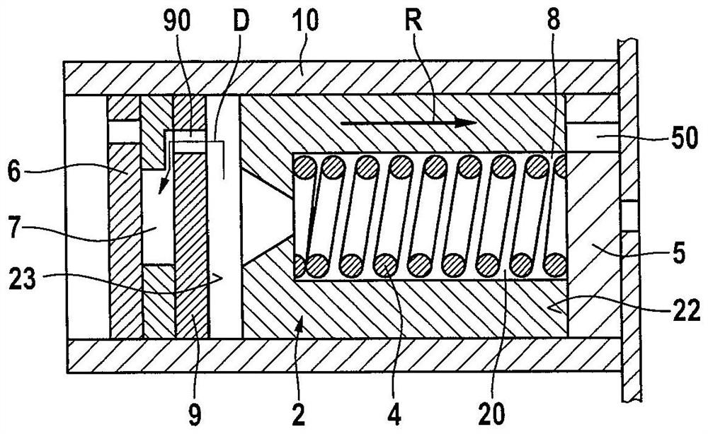
[0024] as from figure 1 As can be seen in , the fuel pump 1 according to the invention is designed as an electromagnetic piston pump and accordingly has a piston 2 , a solenoid coil as actuator 3 for actuating the piston 2 and a magnetic coil as an actuator for actuating the piston 2 . 2 The spring element of the reset element 4 resets into the initial position. The fuel pump 1 according to the invention also comprises a first inlet valve 5 , an outlet valve 6 , a delivery chamber 7 , a prechamber 8 and a second inlet valve 9 .

[0025] The piston 2 is cylindrical and has a through-bore 21 formed therein, which separates the delivery chamber 7 from the pre-chamber 8 , wherein the delivery chamber 7 and the pre-chamber 8 are arranged in a common cylinder component 10 . The piston 2 is likewise arranged in the cylinder component 10 . Fu...


PUM


Abstract

The invention relates to a fuel pump (1) comprising a piston (2), an actuator (3) for operating the piston (2), a reset device for returning the piston (2) into an initial position The element (4), the first inlet valve (5), the outlet valve (6) and the delivery chamber (7), are characterized in that a forestage chamber (8) and a second inlet valve (9) are provided, the second inlet The valve closes or releases the connection between the delivery chamber and the foreline chamber. The invention also relates to a method for the two-stage delivery of fuel by means of a fuel pump ( 1 ) according to the invention.

Description

technical field [0001] The invention relates to a fuel pump for supplying fuel in vehicles such as motorcycles, jet skis or other small motor applications such as chainsaws and a method for operating such a fuel pump. The invention also relates to a fuel tank comprising such a fuel pump. Background technique [0002] Such a fuel pump is for example disclosed by GB 2478876 B. This is a fuel pump, in particular an electromagnetic piston pump, which has a piston, an actuator for actuating the piston, a reset element for restoring the piston into a starting position, an inlet valve, a delivery chamber and an outlet valve. During the suction phase, fuel is sucked through the inlet valve into the delivery chamber by actuation of the piston. During the delivery phase, fuel is delivered from the delivery chamber via the outlet valve. Due to the temperature load, at low suction pressures, fuel can vaporize out at the inlet valve, whereby the delivery chamber is largely filled with...

Claims


Application Information

Patent Timeline
Patent Type & Authority Patents(China)
IPC IPC(8): F02M51/04F02M59/46F04B9/109F04B53/12
CPCF02M51/04F02M59/462F02M59/464F04B17/046
Inventor S·芙洛F·尼切J·阿尔塔莫诺夫W·莫伊雷尔A·克鲁舍T·阿尔盖尔J·科雷克A·普利施
Owner ROBERT BOSCH GMBH
Why Eureka
Try Eureka