Roller-bearing arrangement and a wind turbine

A technology for roller bearings and bearing devices, applied in roller bearings, wind power engines, rolling contact bearings, etc., can solve problems affecting the smooth operation of bearings, and achieve the effects of high stability, less wear and long life

Inactive Publication Date: 2017-02-22
THYSSENKRUPP ROTHE ERDE +1
View PDF8 Cites 4 Cited by
  • Summary
  • Abstract
  • Description
  • Claims
  • Application Information

AI Technical Summary

Problems solved by technology

The disadvantage of this solution is that forces acting perpendicular to the axial direction cause an inclination

Method used


Image

  • Roller-bearing arrangement and a wind turbine
  • Roller-bearing arrangement and a wind turbine

Examples


Embodiment Construction

[0025] In the various figures, identical parts are always provided with the same reference numerals and are therefore usually also specified or mentioned only once in each case.

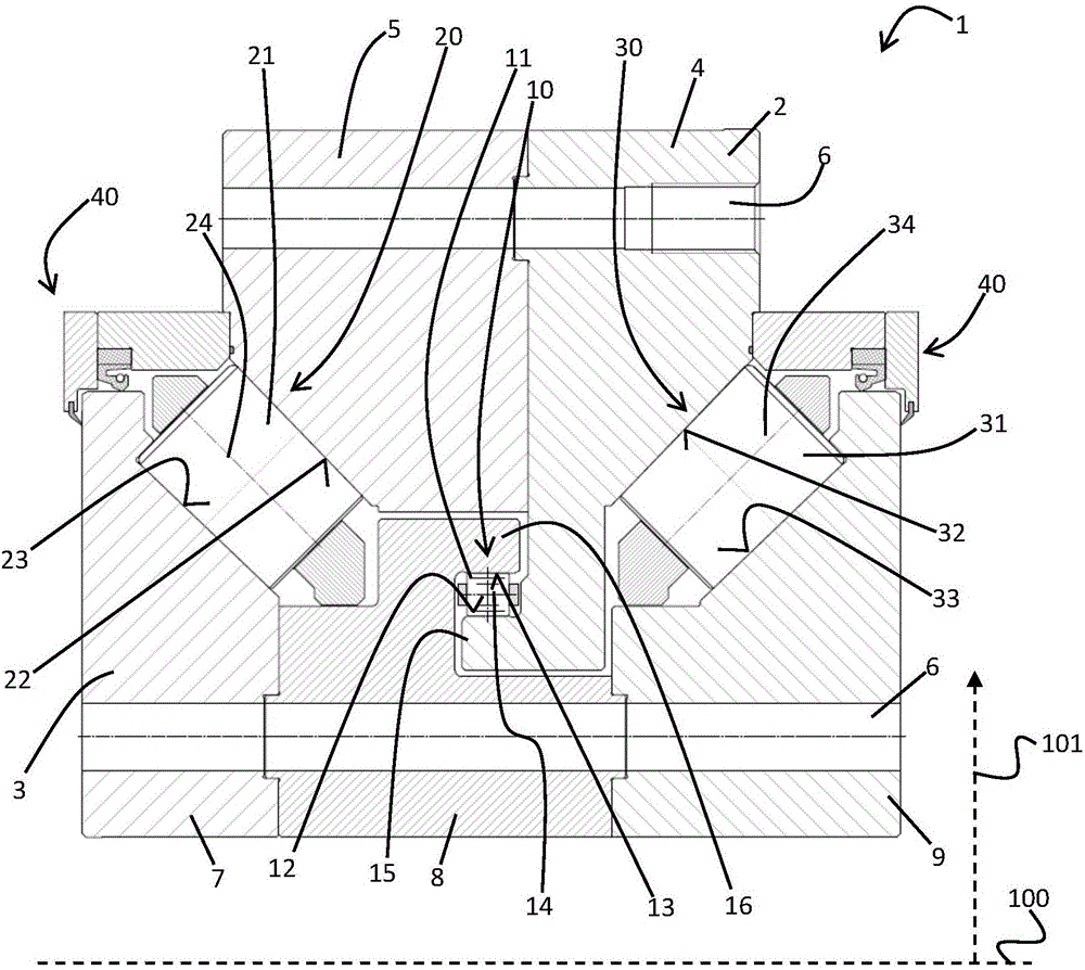
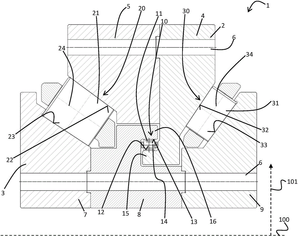
[0026] exist figure 1 , a schematic cross-sectional view of a roller bearing device 1 according to an exemplary first embodiment of the present invention is shown.

[0027] The roller bearing device 1 includes an outer ring 2 and an inner ring 3 . The inner ring 3 is mounted rotatably about an axis of rotation 100 relative to the outer ring 2 . The roller bearing arrangement 1 comprises three bearings: a smaller first bearing in the form of a first raceway 10 fitted with first rolling elements 11 and two substantially symmetrical larger bearings comprising The second raceway 20 fitted with the second rolling body 21 and the third raceway 30 fitted with the third rolling body 31 . The second and third raceways 20, 30 are formed in such a way that the inner ring 3 and the outer ring 2 support each o...


PUM


Abstract

The invention relates to a roller-bearing arrangement, particularly a large-diameter roller-bearing arrangement for a wind turbine, comprising an outer ring and an inner ring that can be rotated about a rotational axis, relative to said outer ring, said roller-bearing arrangement comprising a first raceway in which a plurality of first roller elements are arranged and which is designed between a first ring extension of the outer ring and a second ring extension of the inner ring, said second ring extension engaging behind the first ring extension in a radial direction relative to the rotational axis.

Description

technical field [0001] The invention relates to a roller bearing arrangement according to the preamble of claim 1 . Background technique [0002] Such roller bearing arrangements are well known in the prior art and are used, for example, in the form of so-called large roller bearings for mounting rotor shafts of wind power stations. A wind power station usually comprises a tower and a gondola which is rotatably arranged on the tower and acts as a support for the machine. One end of the rotor shaft arranged in the gondola is connected to the rotor hub with the rotor blades driven by the wind, while the other end is directly or indirectly coupled via a possible transmission to a generator for generating electricity. [0003] The problem with said wind power plants is that, especially in the case of varying wind loads, extremely high axial forces along the rotor shaft and substantially oblique forces perpendicular to the rotor shaft occur in the region of the rotor shaft, requ...

Claims


Application Information

Patent Timeline
IPC IPC(8): F03D80/70F16C19/38F16C19/50
CPCF16C19/38F16C19/386F16C19/505F16C2300/14F16C2360/31
Inventor S·洛夫勒J-P·博赫特T·汉德拉克B·吕内堡W·克劳斯
Owner THYSSENKRUPP ROTHE ERDE
Why Eureka
Try Eureka