Method for characterizing mode group properties of multimodal light traveling through optical components

A technology of optical components and modes, applied in the field of optical fiber transmission, can solve the problem of not allowing to evaluate the individual behavior of mode groups

Active Publication Date: 2017-02-22
DRAKA COMTEQ BV
View PDF7 Cites 2 Cited by
  • Summary
  • Abstract
  • Description
  • Claims
  • Application Information

AI Technical Summary

Problems solved by technology

However, this method does not allow to evaluate the individual behavior of the mode populations as they pass through the optical component

Method used


Image

  • Method for characterizing mode group properties of multimodal light traveling through optical components
  • Method for characterizing mode group properties of multimodal light traveling through optical components
  • Method for characterizing mode group properties of multimodal light traveling through optical components

Examples


Embodiment Construction

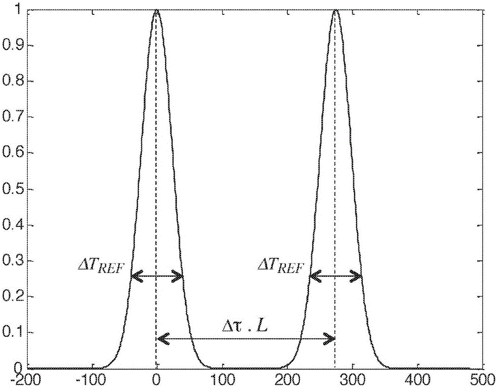
[0139] The general principle of the invention relies on the use of a specially designed mode group separation fiber inserted in the optical path between the light source and the optical component under test and having The ability to separate these mode groups in the temporal domain before or after the component. As a result, the behavior of these mode groups as they pass through optical components can be studied independently of each other.

[0140] Thus, embodiments of the present invention provide a simple and valuable method for characterizing the mode group properties of multimode light passing through an optical component. The experimental results so realized can be used to improve the design of multi-mode fiber and few-mode fiber as well as the design of optical components.

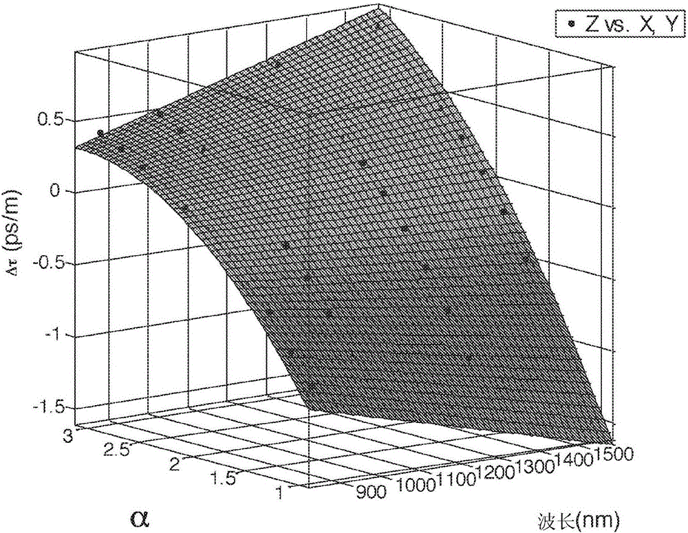
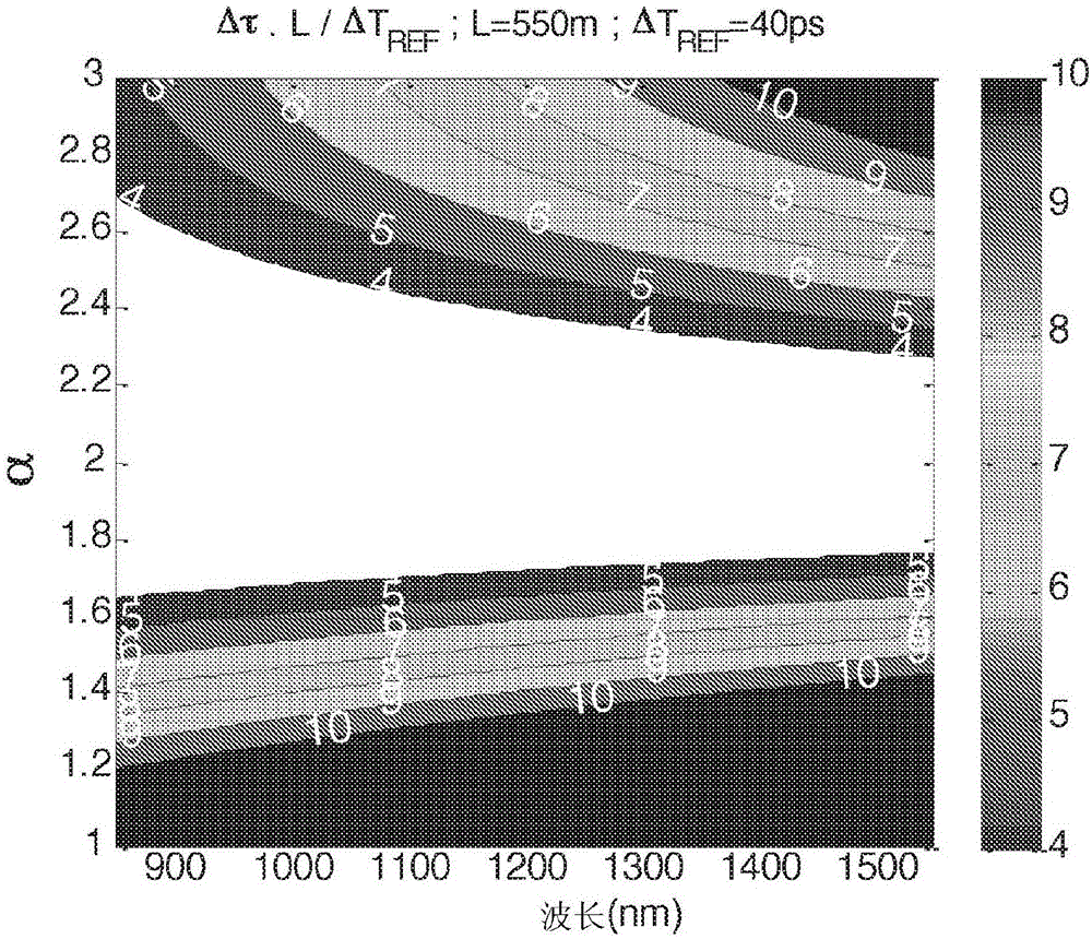
[0141] Figure 1~6 The characteristics of the mode group separation fiber according to the embodiment of the present invention will be described.

[0142] As stated earlier in this document, in an...


PUM


Abstract

The invention concerns a method for characterizing mode group properties of multimodal light traveling through an optical component, comprising: - providing a Mode Group Separating optical fiber in an optical path between a light source and said optical components - launching reference pulses of light with a wavelength [lambda]t from said light source through said Mode Group Separating optical fiber into said optical component at discrete intervals between a core center and a core radius of said fiber. The Mode Group Separating optical fiber is a multimode fiber with an a-profile graded index core with an alpha-value chosen such that said fiber satisfies the following criterion at the wavelength [lambda]t: formula (I) where: - [delta] is a time delay difference between consecutive mode groups; - L is a length of said fiber; - [delta]T REF is a Full Width at Quarter Maximum of said reference pulses.

Description

technical field [0001] The present invention relates to the field of optical fiber transmission, and more particularly to a method for characterizing the mode group properties of multimode light passing through an optical component for use in such optical fiber transmission. Background technique [0002] Multimode fiber is successfully used in high speed data networks. However, multimode fibers suffer from intermodal dispersion due to the fact that, for a particular wavelength, multiple light modes propagate simultaneously along the fiber carrying the same information, but travel at different propagation velocities. Modal dispersion is expressed in the form of Differential Mode Delay (DMD), where the Differential Mode Delay (DMD) is the pulse delay (ps / m) between the fastest mode and the slowest mode passing through the fiber measure of difference. [0003] To minimize modal dispersion, multimode optical fibers used in data communications typically include a core exhibitin...

Claims


Application Information

Patent Timeline
Patent Type & Authority Applications(China)
IPC IPC(8): G02B6/028G02B6/036
CPCG02B6/0288G02B6/0365G01J9/00G01J2009/004G01J2009/006G01M11/338G02B6/14
Inventor F·J·阿赫滕D·莫林P·斯拉德M·比戈-阿斯楚克
Owner DRAKA COMTEQ BV
Why Eureka
Try Eureka