Contact device of a starter contactor

A contact device and starter technology, applied in emergency protection devices, contacts, relays, etc., can solve problems such as plate wear, contact rods that cannot be allowed, deformation, etc., and achieve the effect of low production cost and low risk of scrapping

Active Publication Date: 2017-02-22
VALEO EQUIP ELECTRIC MOTEUR
View PDF7 Cites 3 Cited by
  • Summary
  • Abstract
  • Description
  • Claims
  • Application Information

AI Technical Summary

Problems solved by technology

However, implementation of this type of embodiment is complicated because forcefully inserting the pin into the shaft can damage it during assembly
Also, compared to other embodiments, there are two parts to be assembled instead of one, thus making the assembly more complicated
Furthermore, this type of assembly may not allow the contact rods to be supported on a fixed core
In fact, in this type of embodiment, in the rested state, it is the plate that is supported on a fixed core, which can lead to its deformation
[0008] Furthermore, in all of these embodiments, as well as in prior art embodiments, the springs of the plate that compress against the terminals may become out of alignment with respect to the rod, causing the springs on the plate to press against the terminals. Unbalance of force by terminal
This leads to a risk of arcing between the plate and the terminal, as the plate is inclined and thus makes contact with one terminal before the other
These arcs cause premature wear of the plates

Method used


Image

  • Contact device of a starter contactor
  • Contact device of a starter contactor
  • Contact device of a starter contactor

Examples


Embodiment Construction

[0055] contactor 1

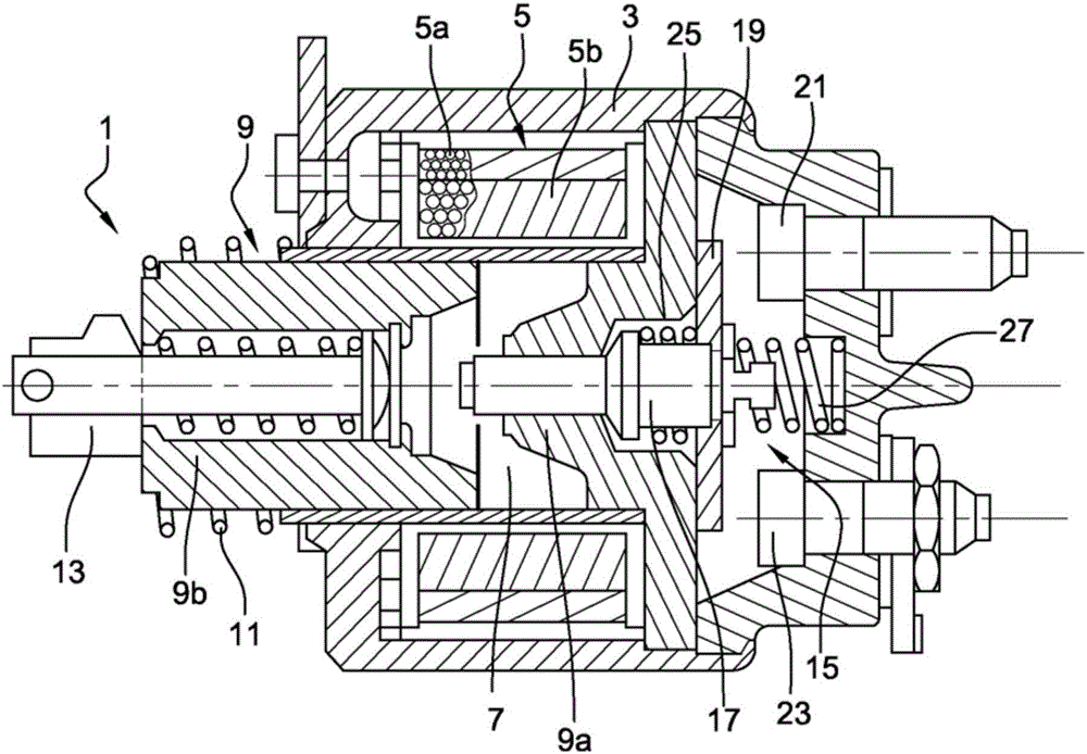
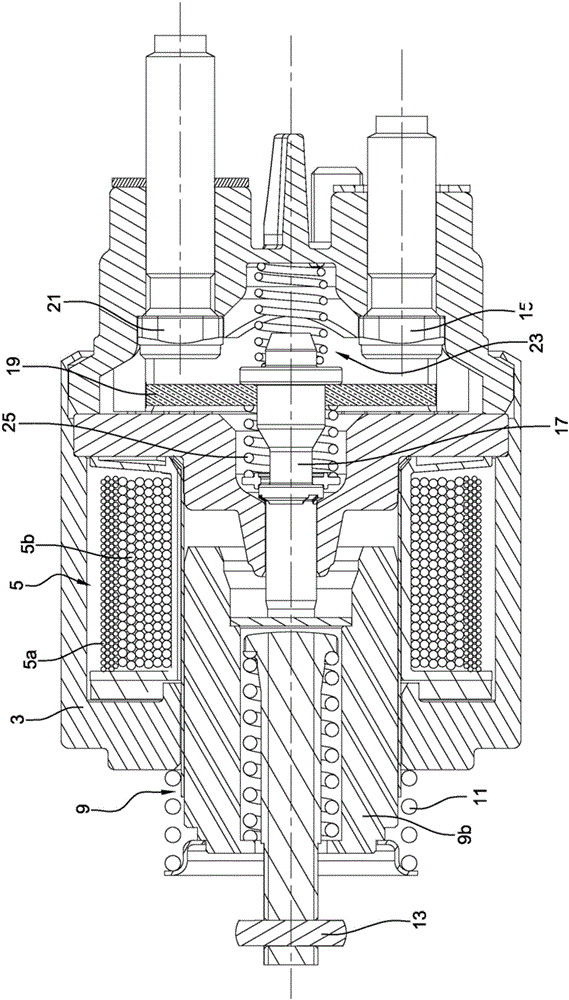
[0056] Figure 1A with 1B Shown is a view of a starter contactor 1 comprising a cover 3 containing a set of coils 5 . The set of coils 5 delimits in its center a tubular cavity 7 in which a magnetic core 9 is arranged. The magnetic core 9 comprises a fixed part 9a and a movable part 9b which can be displaced in translation under the action of the set of coils 5 between a rest position shown in FIG. 1 and an active position, wherein in the active position , the movable portion 9b is in contact with the fixed portion 9a of the magnetic core 9 . Return to the rest position is assisted by the helical spring 11 in the absence of energy supply to the set of coils 5 . The set of coils 5 comprises a pull-in coil 5a and a contact coil 5b, which are energized to displace the movable part 9b of the magnetic core 9 from its rest position to its activated position, which is then 9b is held in the activated position by a separate contact spring 5b, such as to limit ...


PUM


Abstract

The present invention relates to a contact device (15) of a starter contactor (1) comprising: - a contact rod (17) made of an electrically insulating material, - a contact strip (19) made of an electrically conducting material comprising a hole (19a) in which is mounted the contact rod (17), - a squashing spring (25), - a restoring spring (27), the contact device (15) also comprises a closure clip (33) of radial width greater than or equal to the diameter of the squashing spring (25), a radial notch (33a) being made in said closure clip (33), said radial notch (33a) receiving a portion of the contact rod (17), the squashing spring (25) being mounted compressed between the closure clip (33) and the contact strip (19) which is in abutment on a retaining collar (17a) of the contact rod (17).

Description

technical field [0001] The invention relates to the field of starters for thermal engines, in particular for motor vehicles, and more particularly to a contactor of a starter enabling energy to be supplied to an electric motor driving a pinion of the starter. Background technique [0002] The contactor of the starter according to the prior art has two functions, firstly by means of the fork to displace the starter supporting the pinion, such as to allow the pinion to engage the crown of a hot engine to be started, and secondly to Energy is supplied to the electric motor of the starter, enabling it to rotate the pinion. To this end, the contactor comprises a set of coils that enables the displacement of the movable part of the magnetic core, and the movable part of the magnetic core causes the displacement of the fork and the displacement of the contact means, comprising A contact plate designed to establish electrical contact between the supply terminals of an electric moto...

Claims


Application Information

Patent Timeline
Patent Type & Authority Applications(China)
IPC IPC(8): H01H1/20H01H50/30H01H51/06
CPCH01H1/2008H01H50/30H01H51/065H01H50/20H01H50/56H01H2235/01
Inventor R.吉格诺特
Owner VALEO EQUIP ELECTRIC MOTEUR
Why Eureka
Try Eureka