
Rc oscillator based on delay-free comparator

A technology of oscillator and comparator, applied in the field of RC oscillator

Inactive Publication Date: 2017-02-22
QUALCOMM INC
View PDF2 Cites 4 Cited by
  • Summary
  • Abstract
  • Description
  • Claims
  • Application Information

AI Technical Summary

Problems solved by technology

However, this results in an even more current requirement
Therefore, the power efficiency of the RC oscillator makes it impossible to use in low power applications

Method used


Image

  • Rc oscillator based on delay-free comparator
  • Rc oscillator based on delay-free comparator
  • Rc oscillator based on delay-free comparator

Examples


Embodiment Construction

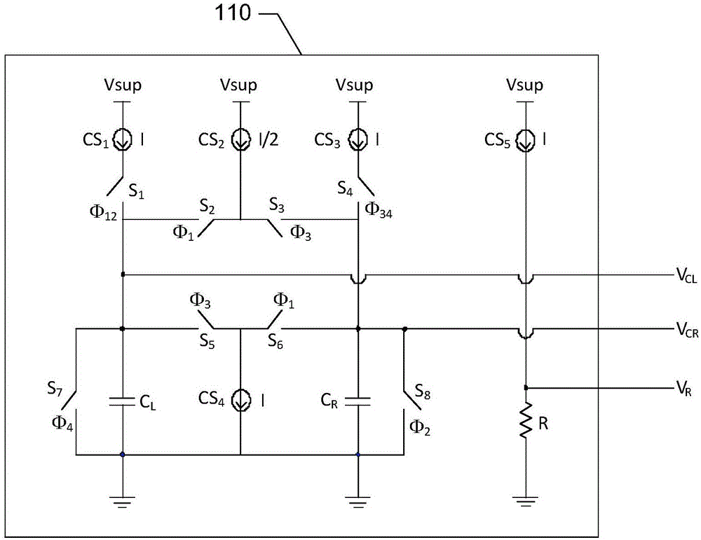
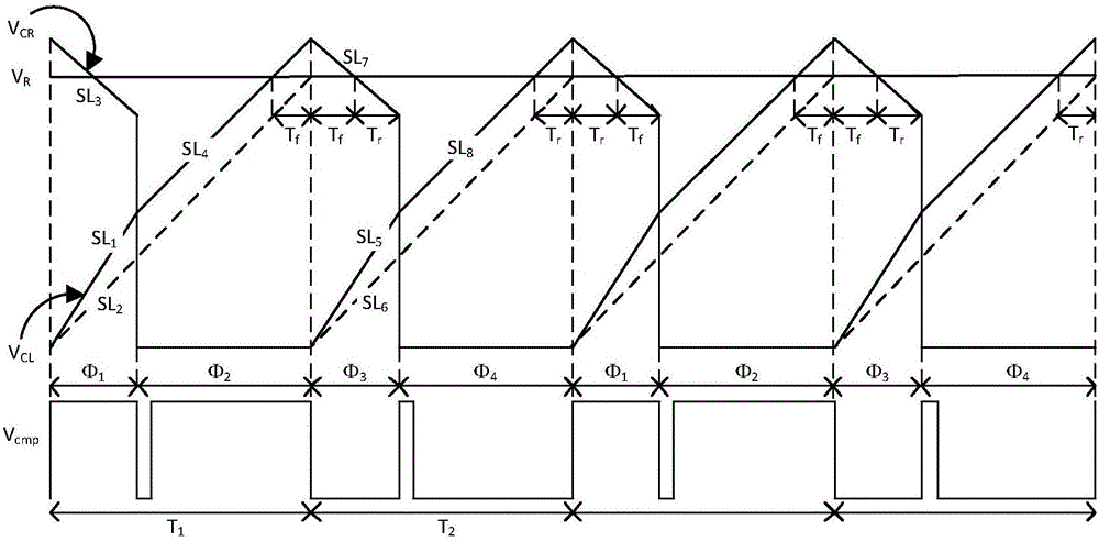
[0024] As mentioned above, RC oscillator is an important block in VLSI system. This RC oscillator provides the reference clock when the crystal oscillator is unavailable or shut down for power saving purposes. However, the frequency accuracy of an RC oscillator is limited by RC process variations, resistor temperature coefficients, and comparator delay variations. In traditional RC oscillator designs, the offset voltage of the comparator is canceled by comparing the two comparator voltages with the resistor voltage. When the voltage on the first capacitor ramps up as the first capacitor is charged by the first charging current, the second capacitor is shorted to ground. A comparator compares the first capacitor voltage to the resistor voltage. At the transition of the comparator, the first capacitor is shorted to ground and the voltage on the second capacitor ramps up as the second capacitor is charged by the second charging current. The comparator now compares the second c...


PUM


Abstract

Cancelling a delay in a comparator of an RC oscillator configured to generate a clock pulse, including: selectively coupling a plurality of current sources to a first capacitor, a second capacitor, and a resistor, wherein the plurality of current source charge and discharge the first capacitor and the second capacitor, and charge the resistor; charging the first capacitor at a higher rate during a first phase of the clock pulse than a second phase of the clock pulse, and charging the second capacitor at a higher rate during a third phase of the clock pulse than a fourth phase of the clock pulse; and generating the clock pulse by enabling the comparator to compare a voltage on the first or second capacitor with a voltage on the resistor.

Description

technical field [0001] The present invention relates to oscillators, and more particularly to an RC oscillator based on a no-delay comparator. Background technique [0002] Resistive-capacitive (RC) oscillators are important blocks in very large-scale integration (VLSI) systems. The RC oscillator provides the reference clock when the crystal oscillator is unavailable or shut down for power saving purposes. However, the frequency accuracy of an RC oscillator is limited by RC process variations, resistor temperature coefficients, and comparator delay variations. [0003] The temperature variation of the comparator delay is the main cause of the frequency variation. Traditionally, the bias current of the comparator is boosted so that the total delay is a fraction of the clock period. However, the comparator delay saturates at high bias currents. To counteract this effect, the device size is increased. However, this results in even more current requirements. Therefore, the...

Claims


Application Information

Patent Timeline
IPC IPC(8): H03K3/0231H03K4/50
CPCH03K3/0231H03K4/50H04B5/00H03K3/30H03B5/04H03B5/20
Inventor 王乐A·梅拉比
Owner QUALCOMM INC
Learn More