High-temperature pressure sensor and manufacturing method thereof

A technology of a pressure sensor and a manufacturing method, which is applied in the measurement, instrument, and measurement force of the property force of piezoelectric resistance materials, can solve the fatigue of thin gold wires or welding places, the problem of stress balance is difficult to eliminate, and the welding points of gold wires are difficult to eliminate. Fatigue, etc.

Pending Publication Date: 2017-03-01
苏州工业园区纳米产业技术研究院有限公司
View PDF8 Cites 14 Cited by
  • Summary
  • Abstract
  • Description
  • Claims
  • Application Information

AI Technical Summary

Problems solved by technology

In addition, Colette also assembles the sensor chip and the protective layer wafer into a sensor diaphragm through electrostatic bonding technology, and then uses high-temperature conductive glass as a circuit connection between the sensor chip and the specially designed joint, which solves the problem of gold wire welding of traditional pressure sensors The problem of easy fatigue, but the stress balance problem after bonding and packaging is still difficult to eliminate
[0007] In summary, the packaging of existing high-temperature pressure sensors mostly

Method used


Image

  • High-temperature pressure sensor and manufacturing method thereof
  • High-temperature pressure sensor and manufacturing method thereof
  • High-temperature pressure sensor and manufacturing method thereof

Examples


Embodiment 1

[0053] Embodiment 1, the manufacturing method of the above-mentioned high-temperature pressure sensor includes the following steps S1 to S5.

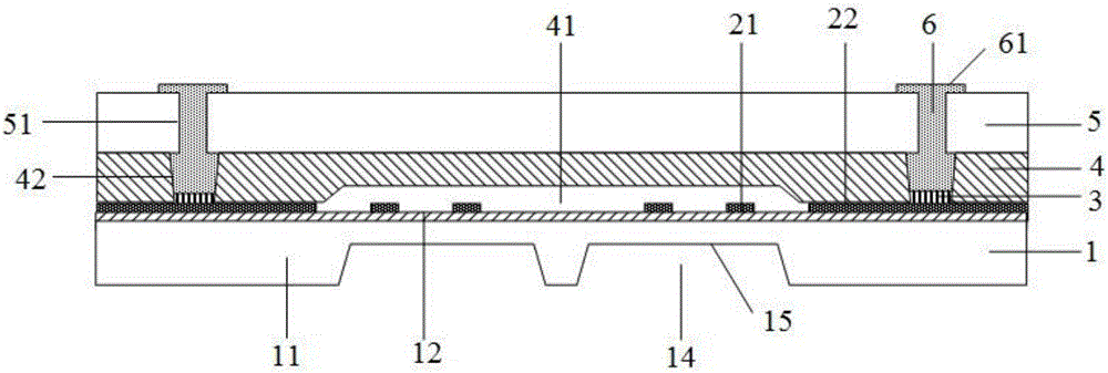
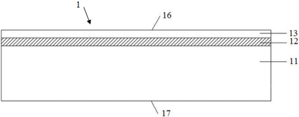
[0054] Please combine figure 2 , S1: providing a silicon substrate 1, the silicon substrate 1 is sequentially provided with a bulk silicon layer 11, an insulating layer 12 and a bulk silicon film 13 from bottom to top, and the silicon substrate 1 has an upper surface 16 and an upper surface 16 arranged opposite to each other. lower surface17. The silicon substrate 1 is an SOI substrate with a crystal orientation.

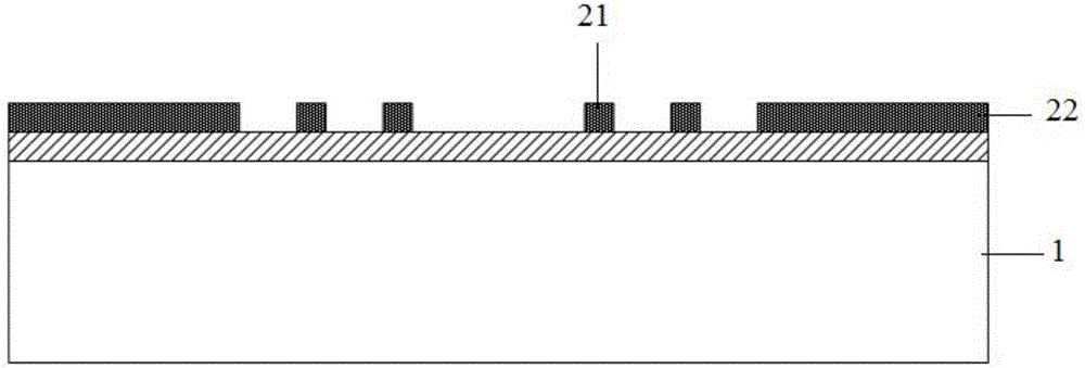
[0055] Please combine image 3 and Figure 4 , S2: forming a sensitive element 21 and a metal electrode 3 electrically connected to the sensitive element 21 on the upper surface (not labeled) of the silicon substrate 1 . The sensitive element 21 is a piezoresistor or a capacitance-based sensitive diaphragm, but in view of the advantages of high sensitivity and good precision, the piezoresistor is preferably a piezoresis...

Embodiment 2

[0067] Embodiment 2, the above-mentioned high-temperature pressure sensor can also adopt the following manufacturing method: including the following steps:

[0068] S1: Provide a silicon substrate, the silicon substrate is sequentially provided with a bulk silicon layer, an insulating layer, and a bulk silicon film from bottom to top, the silicon substrate has an upper surface and a lower surface arranged opposite to each other, the silicon substrate A lower groove is formed on the upper surface;

[0069] S2: forming a sensitive element and a metal electrode electrically connected to the sensitive element on the upper surface of the silicon substrate, the sensitive element is located in the lower groove;

[0070]S3: Provide an intermediate substrate made of high temperature resistant non-conductive material, the intermediate substrate has a front side and a back side arranged opposite to each other, and the back side of the intermediate substrate is bonded to the upper surface...


PUM


Abstract

The invention relates to a high-temperature pressure sensor and a manufacturing method thereof, and belongs to the field of micro-mechanical manufacturing. The high-temperature pressure sensor comprises a silicon substrate, sensitive elements arranged on the substrate, middle substrates, and upper layer silicon sheets. The middle substrates are arranged on the silicon substrate and made of high temperature resisting non-conductive materials. The upper layer silicon sheets are arranged on the middle substrates. The silicon substrate, the middle substrates and the upper silicon sheets are successively bonded. Cavity bodies for collecting the sensitive elements are arranged between the silicon substrate and the middle substrates. According to the invention, the silicon substrate, the middle substrates and the upper silicon sheets are successively superposed to form a silicon substrate-middle substrates-silicon sheets sandwich structure, so stress mismatch is mutually counteracted and stress balancing is achieved; and by adopting the manufacturing method of the high-temperature pressure sensor, the above mentioned effects can be achieved.

Description

technical field [0001] The invention relates to a high-temperature pressure sensor and a manufacturing method thereof, belonging to the field of micro-mechanical manufacturing. Background technique [0002] As one of the main products of micro-electromechanical systems (MEMS), high-temperature resistant pressure sensors have been widely used for pressure measurement in high-temperature environments in petrochemical, automotive electronics, aerospace and other fields. The current commercial pressure sensors are mainly silicon diffused piezoresistive pressure sensors. Because they use single crystal silicon as the substrate, P-type diffused resistors are made on N-type silicon substrates, and rely on reverse-biased PN junctions to achieve electrical isolation. When working When the temperature exceeds 120°C, the leakage current of the PN junction will increase, and the performance of the sensor will seriously deteriorate and even fail. [0003] In addition, high temperature r...

Claims


Application Information

Patent Timeline
IPC IPC(8): G01L1/18G01L1/14
CPCG01L1/14G01L1/18
Inventor 王敏锐孙福河
Owner 苏州工业园区纳米产业技术研究院有限公司
Why Eureka
Try Eureka