High-voltage insulation structure, cable terminal, bus, high-voltage bushing, and transformer bushing
A high-voltage insulation and insulation sleeve technology, which is applied in the fields of cable terminals, busbars, high-voltage bushings and transformer bushings, can solve problems such as multi-equipment, insulation medium leakage, explosion, etc., so as to improve production and installation efficiency and ensure insulation Strength and the effect of reducing manufacturing cost
- Summary
- Abstract
- Description
- Claims
- Application Information
AI Technical Summary
Problems solved by technology
Method used
Image


Examples
Embodiment 1
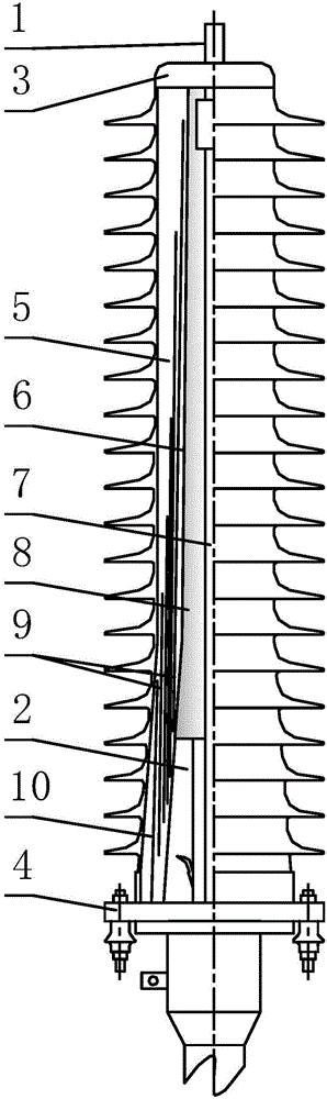
[0024] Such as figure 1 As shown, a capacitive cable terminal not filled with an insulating medium of the present invention includes a conductive rod 1, a stress sleeve 2, a capacitive insulating sleeve 5 with an upper flange 3 and a grounding flange 4, and a capacitive insulating sleeve 5 is tightly crimped with the stress sleeve 2, and the high-voltage equipotential screen 6 embedded in the inner surface of the capacitive insulating sleeve 5 and extending from the upper flange 3 to the top surface of the stress sleeve 2 and the conductive core 7 of the cable form a high-voltage equipotential warehouse 8. The electric field strength in the warehouse is zero. In addition to the high-voltage equipotential screen 6, a group of capacitive screens 9 that are insulated from each other are embedded in the insulating layer of the capacitive insulating sleeve. The outermost grounding screen 10 and the lower flange are The grounding flange 4 is connected, and along the outer surface of...
Embodiment 2
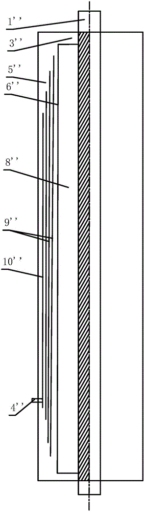
[0029] see figure 2 , the transformer bushing not filled with insulating medium of the present invention includes a conductive rod 1', a stress sleeve 2', an insulating sleeve 5' with an upper flange 3' and a grounding flange 4' at both ends; The conductive rod insulation layer 7' is covered on it, and the insulating sleeve 5 surrounds the conductive rod 1 and the conductive rod insulating layer 7' for insulation protection, forming a closed insulating space between the insulating sleeve 5' and the conductive rod 1' ;The upper flange 3' fixes one end of the insulating sleeve 5' to the conductive rod 1', the stress sleeve 2' is set on the other end of the conductive rod 1' corresponding to the grounding flange, and the other end of the insulating sleeve 5' The grounding flange 4' of the upper flange 4' is connected to the grounding part of the stress sleeve 2', and the insulating sleeve 5' contains the stress sleeve 2' and is tightly crimped with each other, forming a closed s...
Embodiment 3
[0036] Specifically as image 3 As shown, an insulated bus bar according to the third embodiment of the present invention, the tubular conductor 1" of the insulated bus bar is provided with an insulating sleeve 5", and a closed insulating space is formed between the tubular conductor 1" and the insulating sleeve 5". A high-voltage equipotential screen 6" is inlaid on the inner surface of the sleeve 5", and the tubular conductor 1" is electrically connected to the high-voltage equipotential screen 6", forming a gap between the high-voltage equipotential screen 6" and the insulating layer 7" without filling the insulating medium. The high-voltage equipotential chamber is 8", and the insulating layer of the insulating sleeve 5" is also embedded with a plurality of mutually insulated capacitive screens 9", and the outermost capacitive screen is used as a grounding screen 10" to connect to the grounding terminal 4'. Multiple capacitors The axial dimension of the screen 9' is shorte...
PUM
 Abstract
Description
Claims
Application Information
 - R&D
- Intellectual Property
- Life Sciences
- Materials
- Tech Scout
- Unparalleled Data Quality
- Higher Quality Content
- 60% Fewer Hallucinations
Browse by: Latest US Patents, China's latest patents, Technical Efficacy Thesaurus, Application Domain, Technology Topic, Popular Technical Reports.
© 2025 PatSnap. All rights reserved.Legal|Privacy policy|Modern Slavery Act Transparency Statement|Sitemap|About US| Contact US: help@patsnap.com