Power converter

A technology for power converters and transformers, which is used in output power conversion devices, DC power input conversion to DC power output, instruments, etc. , low device loss, easy to achieve effect

Active Publication Date: 2017-03-01
EMERSON NETWORK POWER CO LTD
View PDF5 Cites 2 Cited by
  • Summary
  • Abstract
  • Description
  • Claims
  • Application Information

AI Technical Summary

Problems solved by technology

Therefore to guarantee figure 1 For the normal operation of the resonant converter shown, it is necessary to select a resonant inductor and a resonant capacit

Method used


Image

  • Power converter
  • Power converter
  • Power converter

Examples


Example Embodiment

[0021] Example 1:

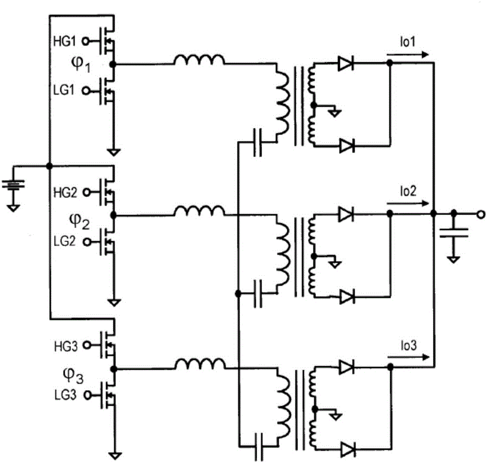
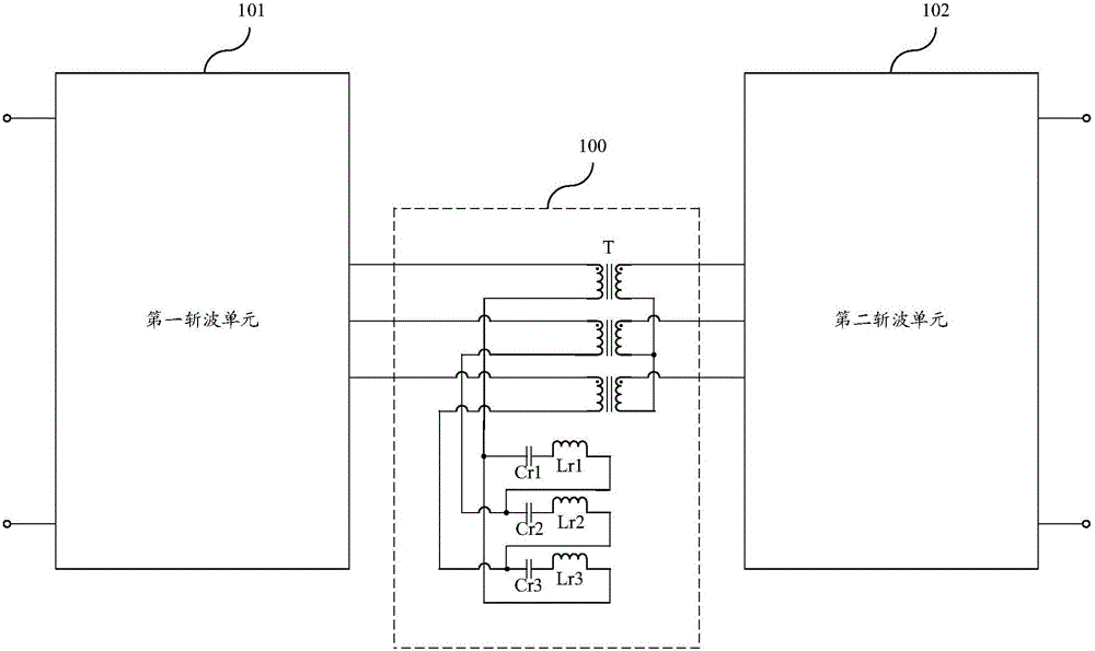
[0022] Embodiment 1 of the present invention provides a power converter, such as figure 2 , image 3 As shown, the power converter includes a first chopping unit 101, a resonant unit 100, and a second chopping unit 102 connected in sequence. The resonant unit 100 includes three sets of resonant inductors Lr1, Lr2, Lr3, and three sets of resonant capacitors Cr1, Cr2, Cr3 and transformer sub-unit T. Transformer sub-unit T includes three first windings and three second windings, among which:

[0023] Each set of resonant capacitors and a set of resonant inductors are connected in series to form a series branch; the three sets of resonant capacitors Cr1, Cr2, Cr3 and three sets of resonant inductors Lr1, Lr2, Lr3 form a triangular connection, that is, a delta connection , Constitute the first angular branch;

[0024] In the first angular branch, the connection nodes of every two series branches are connected to the first end of a first winding of the transformer sub...

Example Embodiment

[0045] Example 2:

[0046] Embodiment 2 of the present invention provides a power converter, such as Figure 5 , Image 6 As shown, the power converter includes a first chopping unit 201, a resonant unit 200, and a second chopping unit 202 that are sequentially connected. The resonant unit 200 includes three sets of resonant inductors Lr1, Lr2, Lr3, and three sets of resonant capacitors Cr1, Cr2, Cr3 and transformer sub-unit T. Transformer sub-unit T includes three first windings and three second windings, among which:

[0047] The three groups of resonant inductors Lr1, Lr2, Lr3 are connected in a triangle shape, that is, connected in a delta shape, forming the first angular branch;

[0048] Each group of resonant capacitors and a first winding of the transformer subunit T are connected in series to form a series branch; the three groups of resonant capacitors Cr1, Cr2, Cr3 and the three first windings of the transformer subunit T form three series branches;

[0049] In the first ang...


PUM


Abstract

The invention provides a power converter. The power converter comprises a first chopper unit, a resonance unit and a second chopper unit, which are successively connected. The resonance unit comprises three groups of resonance inductors, three groups of resonant capacitors and transformers subunits. Each of the transformer subunits comprises three first windings and three second windings. Each group of the resonance capacitors and one group of the resonance inductors are serially connected to form a serially connection branch. Three serially connected branches formed by three groups of the resonance capacitors and three groups of resonance inductors are connected in a triangular manner, so a first angle-shaped branch is formed. In the first angle-shaped branch, a wiring node of every two serially connected branches is connected with a first end of one first winding of the corresponding transformer subunit. Second ends of the three first windings of each transformer subunit are connected with the first chopper unit. The three second windings of each transformer subunit are connected with the second chopper unit. According to the invention, compared with the prior art, the type of devices can be quite easily chosen and the devices are quite easily achieved.

Description

technical field [0001] The invention relates to the technical field of power electronics, in particular to a power converter. Background technique [0002] Power converters such as resonant converters have been widely used in various fields due to their high efficiency. A multi-phase resonant converter is disclosed in the Chinese patent "Multiphase Resonant Converter and Its Controlling Method" with application number 201010261397.1, which includes a first chopping unit, a resonant unit and a second chopping unit , see the specific structure figure 1 shown. Among them, the resonant unit includes three sets of resonant inductors, three sets of resonant capacitors and transformer subunits, each set of resonant inductors, a primary winding of the transformer subunit, and a set of resonant capacitors are connected in series to form a branch circuit, three sets of resonant inductors, three sets of resonant The three branches formed by the capacitor and the three primary windin...

Claims


Application Information

Patent Timeline
IPC IPC(8): H02M3/335
CPCY02B70/10
Inventor 胡永辉是亚明
Owner EMERSON NETWORK POWER CO LTD
Why Eureka
Try Eureka