Medical devices with non-uniform coatings for enhanced echogenicity
A technology for medical devices and coatings, applied in the fields of physics, biology, and medicine, can solve the problems of difficult to obtain ultrasonic imaging coatings, difficult to control the concentration and size of bubbles, etc.
- Summary
- Abstract
- Description
- Claims
- Application Information
AI Technical Summary
Problems solved by technology
Method used
Image
Examples
Embodiment 1
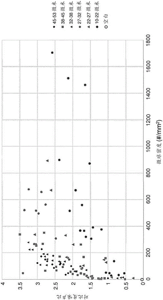
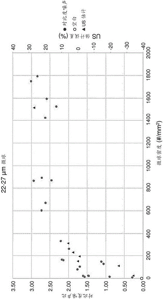
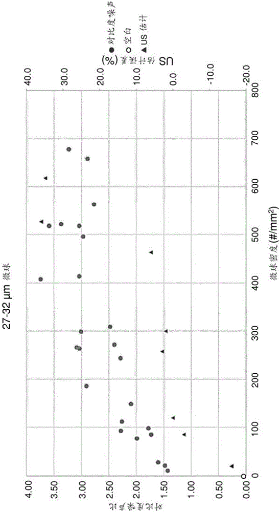
[0130] Commercially available solid glass microspheres (from Cospheric) ranging in diameter from 10 μm to 22 μm, 22 μm to 27 μm, 27 μm to 32 μm, 32 μm to 38 μm, 38 μm were thoroughly mixed in the polyurethane coating matrix to 45 μm and 45 μm to 53 μm, all of the solid glass microspheres have a density of 2.5 g / mL. Microspheres were added in varying amounts to prepare mixtures containing 0.5 vol.% to 75.0 vol.% microspheres in the coating matrix. Subsequently, coating films of 30 μm or 60 μm thickness were drawn on both glass slides and PEBAX 6233 sheets as substrates using a film maker. It has been determined that the density of the microspheres ranges from 2 particles / mm 2 Up to 1831 particles / mm 2 Variety.
[0131] Coated substrates were measured ultrasonically using a 33 mm line array probe operated in brightness mode (B-mode) at 6 MHz. At an angle of approximately 45 degrees, the substrate was placed within a commercially available ultrasonic phantom that served as th...
Embodiment 2
[0137] Commercially available solid glass microspheres ranging in diameter from 10 μm to 22 μm, 22 μm to 27 μm, 27 μm to 32 μm, 32 μm to 38 μm, 38 μm to 45 μm, and 45 μm were thoroughly mixed in the polyurethane coating matrix All of the solid glass microspheres have a density of 2.5 g / mL to 53 μm. Microspheres were added in varying amounts to prepare mixtures containing 0.5 vol.% to 75.0 vol.% microspheres in the coating matrix. Subsequently, 30 μm or 60 μm thick test strips were drawn on glass slides using a film maker. These test strips were applied by masking the areas that were not to be coated. Measure the width of the test strip.
[0138] Coated substrates were measured ultrasonically using a 33 mm line array probe operated in brightness mode (B-mode) at 6 MHz. At an angle of approximately 45 degrees, the substrate was placed within a commercially available ultrasound body membrane that served as the medium.
[0139] Determine the width of the test strip visible und...
Embodiment 3
[0150] Solid glass microspheres ranging in diameter from 38 to 45 μm with a density of 2.5 g / mL were thoroughly mixed in the polyurethane coating matrix as described above. These particles were subsequently coated on glass slides and plastic (PEBAX 6233) at different densities. Coated substrates were measured ultrasonically using a 33 mm line array probe operated in brightness mode (B-mode) at 6 MHz. At an angle of approximately 45 degrees, the substrate was placed within a commercially available ultrasound body membrane that served as the medium. In the same manner as described in Example 1, the contrast-to-noise ratio (CNR) was determined from the recorded images, and the determined CNR was plotted against the microsphere concentration ( Figure 7 ).
[0151] Such as Figure 7 As can be seen in , the CNR values for glass and plastic coated with the same amount of particles are comparable. This confirms that the material of the surface used does not significantly affect...
PUM
| Property | Measurement | Unit |
|---|---|---|
| diameter | aaaaa | aaaaa |
| diameter | aaaaa | aaaaa |
| diameter | aaaaa | aaaaa |
Abstract
Description
Claims
Application Information
 - R&D
- Intellectual Property
- Life Sciences
- Materials
- Tech Scout
- Unparalleled Data Quality
- Higher Quality Content
- 60% Fewer Hallucinations
Browse by: Latest US Patents, China's latest patents, Technical Efficacy Thesaurus, Application Domain, Technology Topic, Popular Technical Reports.
© 2025 PatSnap. All rights reserved.Legal|Privacy policy|Modern Slavery Act Transparency Statement|Sitemap|About US| Contact US: help@patsnap.com


