
Wedge frame and dynamic compaction machine

A wedge and boom technology, applied in cranes, soil protection, construction, etc., can solve the problems of small angle between luffing rope and boom, shortened working life, smaller angle between luffing rope and boom, etc. Achieve the effect of improving work stability, improving service life, and optimizing the way of force transmission

Active Publication Date: 2018-07-17
XCMG CONSTR MACHINERY
View PDF6 Cites 0 Cited by
  • Summary
  • Abstract
  • Description
  • Claims
  • Application Information

AI Technical Summary

Problems solved by technology

[0004] However, the support frame of the existing dynamic compaction machine mostly adopts the form of acute-angled triangle hinged structure. The top of the front strut and the rear tie rod in the support frame are fixed with luffing pulleys, and the bottom end is hinged to the rear end of the turntable. Due to the limitation of convenient installation, the included angle between the luffing rope and the jib frame is small, the pulling force on the luffing rope is relatively large when the rammer is lifted, and the stored energy (deformation energy) is also large. After the rammer is unhooked, it is stored in the The energy in the rope is released instantaneously, the swing range of the boom is still relatively large, the shaking of the whole machine is obvious, and the weak parts are easily damaged, which reduces the working stability and service life of the whole machine
At present, there is no standard for the manufacture of the support frame. If the size is increased blindly, the stiffness will decrease and the cost will increase; After decoupling, the swing range of the arm frame increases, the working stability of the whole machine deteriorates, the risk of damage to weak parts increases, and the working life decreases

Method used

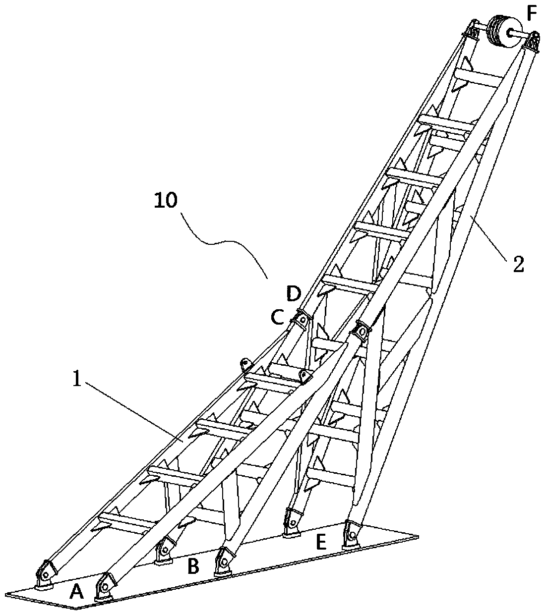
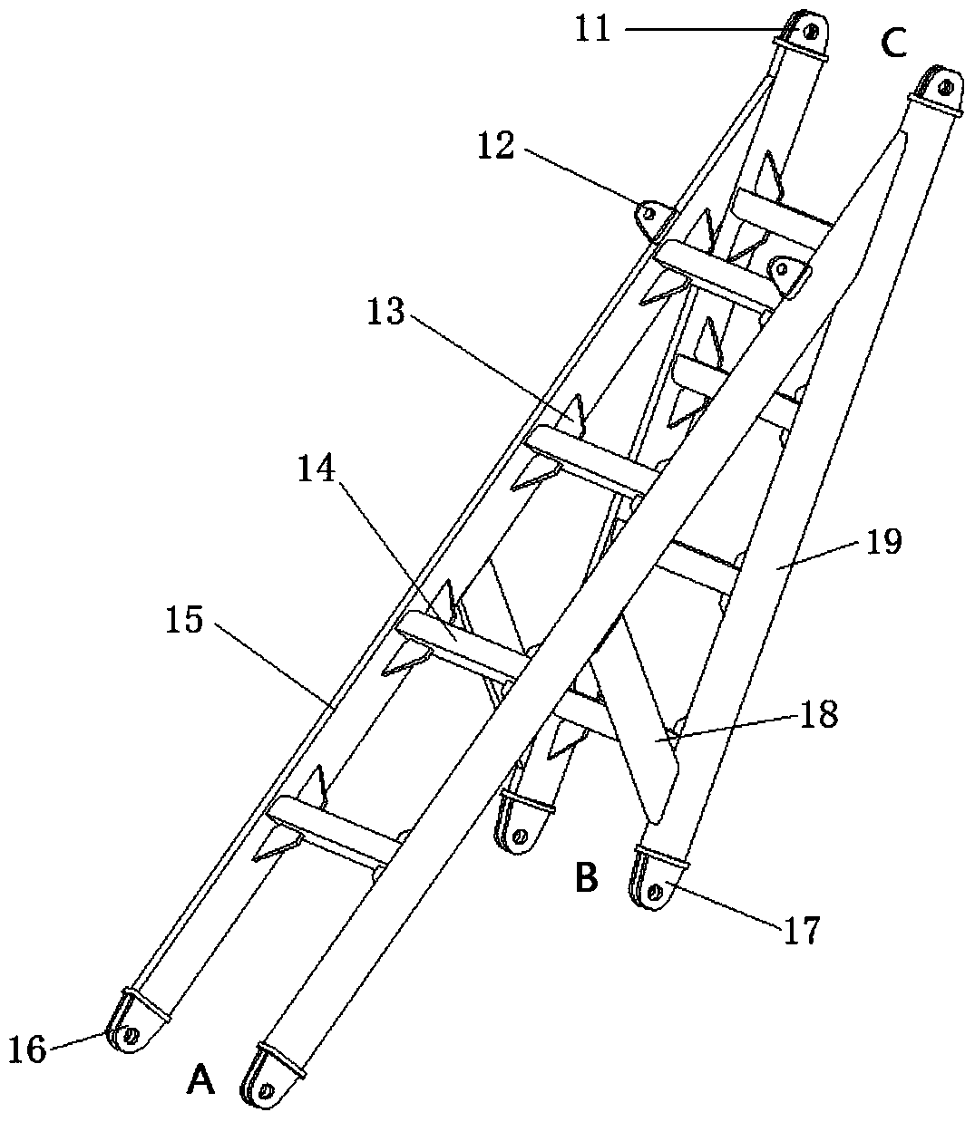
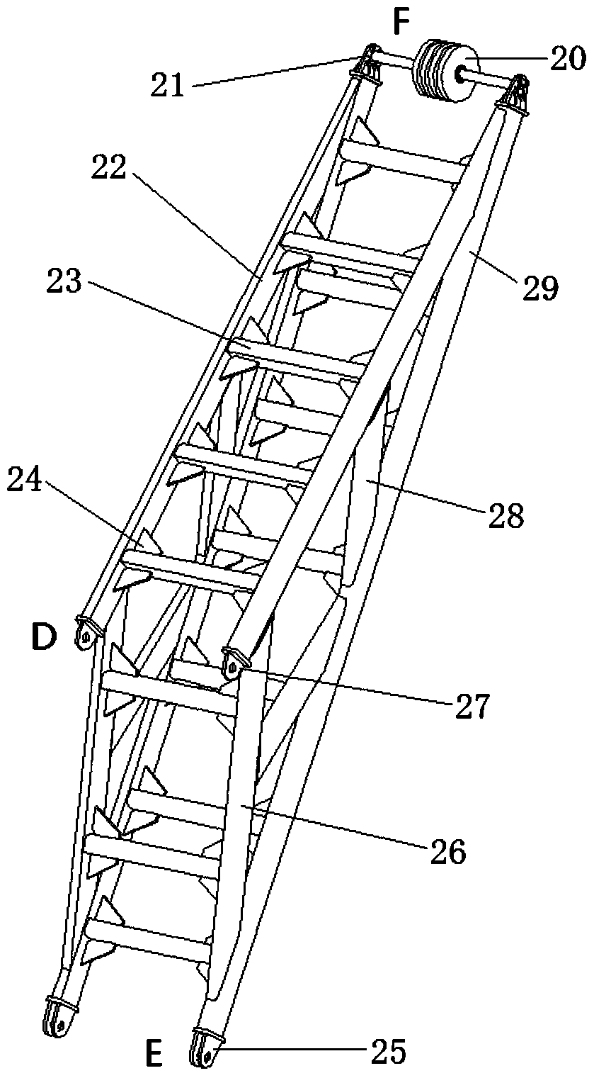

Image

  • Wedge frame and dynamic compaction machine
  • Wedge frame and dynamic compaction machine
  • Wedge frame and dynamic compaction machine

Examples


Embodiment Construction

[0025] The technical solutions in the embodiments of the present invention will be clearly and completely described below in conjunction with the drawings in the embodiments of the present invention. Apparently, the described embodiments are only some of the embodiments of the present invention, not all of them. Based on the embodiments of the present invention, all other embodiments obtained by persons of ordinary skill in the art without making creative efforts fall within the protection scope of the present invention.

[0026] In describing the present invention, it should be understood that the terms "center", "transverse", "longitudinal", "front", "rear", "left", "right", "upper", "lower", " The orientations or positional relationships indicated by "vertical", "horizontal", "top", "bottom", "inner" and "outer" are based on the orientations or positional relationships shown in the drawings, and are only for the convenience of describing the present invention and Simplifie...


PUM


Abstract

The invention relates to a wedge-shaped frame and a dynamic compaction machine. The wedge-shaped frame is installed on a rotating table. An arm frame is arranged at the front end of the rotating table. A balance weight is arranged at the rear end of the rotating table. The wedge-shaped frame comprises a first assembly and a second assembly. The first assembly is provided with a front hinge point set, a rear hinge point set and an upper hinge point set. The second assembly is provided with a lower hinge point set and a middle hinge point set. The front hinge point set and the rear hinge point set are hinged to the positions, close to the front edge and the rear edge of the outer edge outline of a rotation support of the rotating table, of the upper surface of the rotating table correspondingly. The lower hinge point set is hinged to the position, close to the front end face of the balance weight, of the upper surface of the rotating table. The upper hinge point set is hinged to the middle hinge point set. A pulley set winding around a stay rope is arranged on the top of the second assembly. According to the wedge-shaped frame, at least three sets of hinge points are arranged between the wedge-shaped frame and the rotating table, at the moment when a pounder is unhooked, leaning-back impact force of the arm frame is transferred to the position under a vehicle through the first assembly, the rotating table and the rotating support and finally to the ground, and the force transmission path is optimized.

Description

technical field [0001] The invention relates to the technical field of engineering machinery, in particular to a wedge frame and a dynamic compaction machine. Background technique [0002] The dynamic compaction machine is a kind of large-scale construction machinery construction equipment that uses the principle of dynamic compaction to raise the rammer to a certain height through the lifting mechanism, and then releases the compacted foundation to enhance the bearing capacity of the foundation. It is widely used in roads, railways, airports, docks, Land reclamation from the sea, backfilling in mountainous areas and other foundation treatments. The equipment has the characteristics of high operating frequency, frequent impact loads, and harsh working conditions on the job site. After the boom is suddenly unloaded, the energy stored in the whole machine, especially the energy stored in the cable stay of the boom on the whole machine, is rammed The falling off of the hammer ...

Claims


Application Information

Patent Timeline
Patent Type & Authority Patents(China)
IPC IPC(8): B66C23/78B66C23/62E02D3/046
CPCB66C23/62B66C23/78E02D3/046
Inventor 李怀勇王素景郭英训朱发浩
Owner XCMG CONSTR MACHINERY
Learn More