Split gate piers and split bridge piers
A technology of splitting and gate piers, which is applied in the direction of bridges, bridge parts, bridge construction, etc., can solve problems such as inability to ensure safe operation of the project, damage to the foundation of the pier body, and loss of stability of the project, so as to reduce the phenomenon of flooding and reduce The effect of small lateral resistance and simple structure
- Summary
- Abstract
- Description
- Claims
- Application Information
AI Technical Summary
Problems solved by technology
Method used
Image
Examples
Embodiment 1
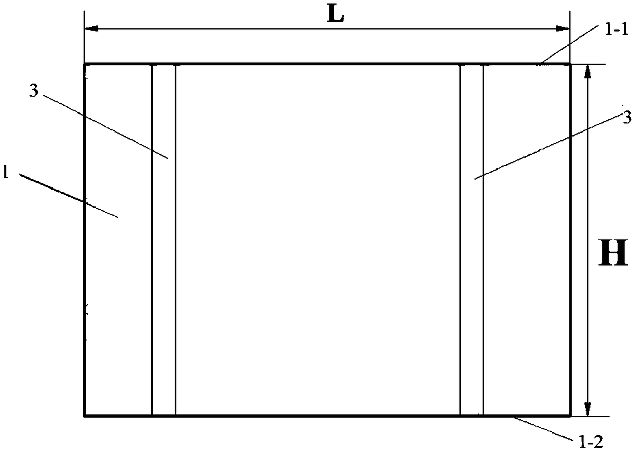
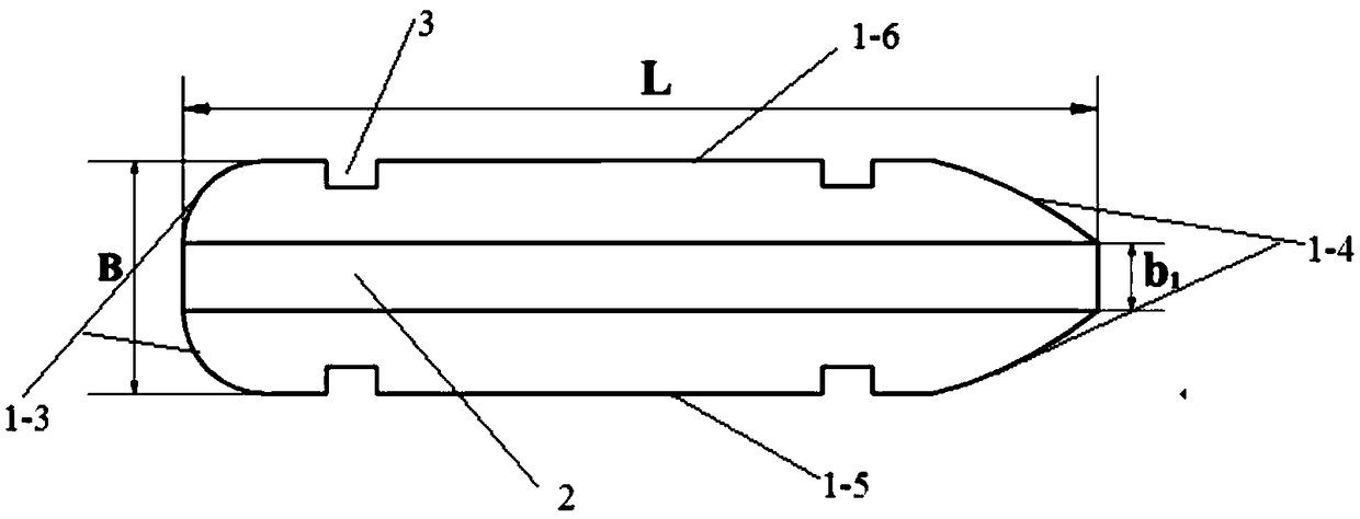
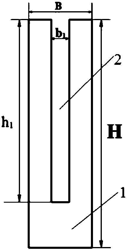
[0048] The longitudinally split gate pier described in this embodiment has the shape and structure as follows Figure 1-Figure 3 As shown, it consists of a pier body 1, which has a top surface 1-1, a bottom surface 1-2, an upstream end surface 1-3, a downstream end surface 1-4, a front side surface 1-5 and a rear side surface 1-6. The top surface 1-1 and the bottom surface 1-2 of the body are horizontal planes, the front side surface 1-5 and the rear side surface 1-6 are vertical planes and are provided with a gate groove 3, the upstream end surface 1-3 is an arc surface, and the downstream end surface 1- 4 is a streamlined surface, the pier body is provided with a longitudinal slit 2, the longitudinal slit 2 penetrates the top surface and the upstream end face and the downstream end face of the pier body, and its center line coincides with the longitudinal center line of the pier body. The width of the pier body is B=6.0m, the height of the pier body is H=50m, the length of t...
Embodiment 2
[0054] In this embodiment, the transversely-slit gate piers are as follows: Figure 4-Figure 6 As shown, it consists of a pier body 1, which has a top surface 1-1, a bottom surface 1-2, an upstream end surface 1-3, a downstream end surface 1-4, a front side surface 1-5 and a rear side surface 1-6. The top surface 1-1 and the bottom surface 1-2 of the body are horizontal planes, the front side surface 1-5 and the rear side surface 1-6 are vertical planes and are provided with a gate groove 3, the upstream end surface 1-3 is a semicircular surface, and the downstream end surface 1 -4 is a streamlined surface, the pier body is provided with a transverse slit 4, the transverse slit 4 runs through the top surface, front side and rear side of the pier body, and its center line coincides with the transverse center line of the pier body. The width of the pier body is B=6.0m, the height of the pier body is H=50m, the length of the pier body is L=30m, and the width of the transverse sea...
Embodiment 3
[0060] The cross-slit bridge pier structure described in this embodiment is as follows: Figure 16-Figure 18 As shown, it consists of a pier body 1, which has a top surface 1-1, a bottom surface 1-2, an upstream end surface 1-3, a downstream end surface 1-4, a front side surface 1-5 and a rear side surface 1-6. The top surface 1-1 and the bottom surface 1-2 of the body are horizontal planes, the front side surface 1-5 and the rear side surface 1-6 are vertical planes, the upstream end surface 1-3 and the downstream end surface 1-4 are arc-shaped surfaces, and the upper A longitudinal slit 2 and a transverse slit 4 are provided. The longitudinal slit 2 runs through the top surface, the upstream end face and the downstream end face of the pier body, and its center line coincides with the longitudinal center line of the pier body. 4. It runs through the top surface, front side and rear side of the pier body, and its center line coincides with the transverse center line of the pie...
PUM
 Abstract
Description
Claims
Application Information
 - R&D
- Intellectual Property
- Life Sciences
- Materials
- Tech Scout
- Unparalleled Data Quality
- Higher Quality Content
- 60% Fewer Hallucinations
Browse by: Latest US Patents, China's latest patents, Technical Efficacy Thesaurus, Application Domain, Technology Topic, Popular Technical Reports.
© 2025 PatSnap. All rights reserved.Legal|Privacy policy|Modern Slavery Act Transparency Statement|Sitemap|About US| Contact US: help@patsnap.com


