Gravity lever circulation power generator used for self power supply

A technology of wind power generators and generators, applied in the direction of engines, machines/engines, mechanical equipment, etc., can solve problems such as damage to wind blades, failure to guarantee power generation status, power generation time, uncontrollable status, etc., and achieve the effect of simple device structure

Inactive Publication Date: 2017-03-08
沈晓华
View PDF0 Cites 1 Cited by
  • Summary
  • Abstract
  • Description
  • Claims
  • Application Information

AI Technical Summary

Problems solved by technology

[0002] At present, large-scale wind turbines cannot generate electricity when there is no wind or insufficient wind power. Due to the influence of natural conditions, it cannot be guaranteed that they can always be in the state of power generation. Larger areas, in these areas, it is easy to do a little damage to the wind blades. At the same time, the natural wind used, the power generation time and state are uncontrollable, and are limited by environmental conditions.

Method used


Image

  • Gravity lever circulation power generator used for self power supply
  • Gravity lever circulation power generator used for self power supply

Examples


Embodiment 1

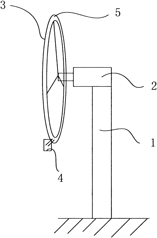
[0025] In the above-mentioned structure, the teeth of the ring gear 3 are internal teeth and arranged to mesh with the gear 41 to realize the lifting of the gravity device 4, so as to achieve the purpose of different power generation.

Embodiment 2

[0027] Similar to the above structure, only the ring gear 3 is set as external teeth, and the relative position of the gear 41 on the gravity device 4 is changed, but its structure is similar to the above structure, and the working method is also set in the same way.

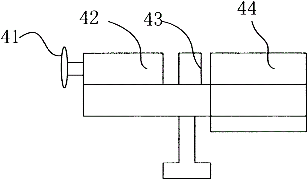
[0028] The sliding block 42 is embedded and slides in the groove ring 5, the sliding block can be loosened by being embedded, and at the same time, the ring gear 3 can run a complete circle to ensure the complete operation of the fan blade.

[0029] The driving device 43 is composed of a motor and a driving power supply, the driving power supply is connected to the motor, and the rotating shaft of the motor is connected to the gear 41 in rotation, wherein the input end of the driving power supply is connected to the output end of the wind power generator 2 , after the wind turbine 2 sends out the power supply, it only needs to supply a small part of the power to the driving power supply, and the driving power sup...

Embodiment 3

[0032] In the above structure, the mechanical fixed limiter is composed of a fixed limiter and a control switch, the control switch is controlled by the fixed limiter, the control switch is connected to the controller, and the mechanical fixed limiter The device needs to be provided with a limit line at its rear end. When the gravity device 4 rises to the highest position, the limit line pulls the fixed limit piece so that the fixed limit piece is fixed on the ring gear 3. Under reuse, the ring gear 3 is rotated, and after the fixed limiter is rotated to the specified position, the controller will start the driving power to start the motor to make the gear 41 work, and then go up, and at the same time, another gravity device 4 at its relative position is also in contact with the gear 41. The above-mentioned gravity device 4 does the same action, but the actions of the two are in alternate reciprocating motion.


PUM


Abstract

The invention relates to a gravity lever circulation power generator used for self power supply. The gravity lever circulation power generator comprises a main rod. A wind power generator is fixedly arranged on the top of the main rod. A gear ring is arranged on the circumference of a blade on the wind power generator. Groove rings are formed in the two sides of the gear ring correspondingly and are symmetrically formed. Gravity devices are arranged on the groove rings on the two sides correspondingly. The sliding gravity devices slide on the groove rings. The initial positions of the gravity devices are arranged at the lower end of the blade. The end positions of the gravity devices are arranged at the positions forming 90-degree angles together with the initial positions of the gravity devices. The gravity devices arranged on the two sides alternately slide on the groove rings. The device is simple in structure and can continue to generate power in the windless state of the blade, and the gravity lever circulation power generator is greener and more environment-friendly, is not influenced by the environment, is permanently stable and unceasingly generates power in a controllable manner.

Description

technical field [0001] The invention relates to a generator, in particular to a gravity lever cycle generator for self-power supply. Background technique [0002] At present, large-scale wind turbines cannot generate electricity when there is no wind or insufficient wind power. Due to the influence of natural conditions, it cannot be guaranteed that they can always be in the state of power generation. In larger areas, it is easy to damage the wind blades a little bit in these areas. At the same time, the natural wind used, the time and state of power generation are uncontrollable, and are limited by environmental conditions. [0003] In view of the above-mentioned defects, the designer, actively researches and innovates, in order to create a gravity lever cycle generator for self-power supply with a new structure, so that it has more industrial utilization value. Contents of the invention [0004] In order to solve the above technical problems, the object of the present i...

Claims


Application Information

Patent Timeline
IPC IPC(8): F03G3/00
Inventor 沈晓华
Owner 沈晓华
Why Eureka
Try Eureka