Al technical title is built by PatSnap Al team. It summarizes the technical point description of the patent document.
A hydraulic cylinder and self-locking technology, which is applied in the field of hydraulic cylinders, can solve problems such as valve leakage, hydraulic cylinder sealing performance, and inability to lock the piston rod stably, and achieve the effects of slowing down collisions and prolonging service life
Active Publication Date: 2017-03-08
泸州长江液压密封件有限公司
View PDF6 Cites 12 Cited by
Summary
Abstract
Description
Claims
Application Information
AI Technical Summary
This helps you quickly interpret patents by identifying the three key elements:
Problems solved by technology
Method used
Benefits of technology
Problems solved by technology
[0003] The technical problem to be solved by the present invention is that when the piston rod is stabilized at the working position in the traditional way, a hydraulic reversing valve is used to realize the locking of the piston rod, but there is a phenomenon of valve leakage, and the piston cannot be locked stably. Rod, and the buffer method adopted by the traditional buffer piston and the cylinder bottom has an impact on the sealing of the hydraulic cylinder. The purpose is to provide a hydraulic cylinder that uses springs for self-locking to solve the above problems
Method used
Image
Click on the blue label to locate the original text in one second.
Reading with bidirectional positioning of images and text.
Examples
Embodiment
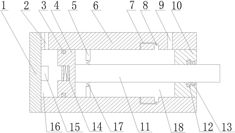
[0020] like figure 1 As shown, the present invention utilizes spring to carry out self-locking hydraulic cylinder, comprises cylinder bottom 1, piston 4, cylinder barrel 6, cylinder head 10 and piston rod 11, and described cylinder barrel 6 is welded with cylinder bottom 1, and cylinder head 10 connects piston 4 is sealed inside the cylinder 6, the piston 4 can move inside the cylinder 6, and the first sealing ring 3 is arranged between the piston 4 and the cylinder 6, the first sealing ring 3 is a rectangular sealing ring, and the rectangular sealing ring The contact pressure is uniform, the sealing area is large, and the sealing effect is good. The piston 4 is also provided with a blind hole, and a buffer device 14 is arranged in the blind hole. The buffer device 14 is composed of a buffer spring and a buffer plate. One end of the buffer spring is connected to the piston 4. , the other end is connected with the buffer plate, a rodless cavity 16 is provided between the piston...
PUM
Abstract
The invention discloses a hydraulic cylinder for self-locking by a spring. The hydraulic cylinder comprises a cylinder barrel, a cylinder bottom, a cylinder cover, a piston and a piston rod; a blind hole is formed in the piston; a buffer device is arranged in the blind hole; a support column is arranged on the cylinder bottom; when the support column is acted on the buffer device, the moving speed of the piston is forced to slow down, so that quick collision between the piston and the cylinder bottom is prevented, and a certain protecting effect is achieved on a hydraulic system; the spring is arranged on the piston rod, and is provided with a locking rod; an oil inlet pipe and a self-locking groove are arranged in the cylinder barrel; when the piston rod moves to a certain position, the locking rod can be clamped into the self-locking groove due to the effect of the spring, and the piston rod is kept still to realize self-locking; and during unlocking, high-pressure oil enters the self-locking groove through the oil inlet pipe, pressure generated by the hydraulic oil can enable the locking rod to shrink back, and the piston rod can move again.
Description
technical field [0001] The invention relates to a mechanical transmission mechanism, in particular to a hydraulic cylinder which utilizes a spring for self-locking. Background technique [0002] Hydraulic transmission has many outstanding advantages, so it is widely used, such as plastic processing machinery, pressure machinery, machine tools, etc. for general industrial use; engineering machinery, construction machinery, agricultural machinery, automobiles, etc. in walking machinery; Metallurgical machinery, hoisting devices, roll adjustment devices, etc.; flood control gates and dam devices, river bed lifting devices, bridge control mechanisms, etc. for civil and water conservancy projects; turbine speed control devices for power plants, nuclear power plants, etc.; deck lifting machinery for ships (Winch), bow door, bulkhead valve, stern propeller, etc.; giant antenna control device for special technology, measuring buoy, lifting and rotating stage, etc.; artillery control...
Claims
Application Information
Patent Timeline
Application Date:The date an application was filed.
Publication Date:The date a patent or application was officially published.
First Publication Date:The earliest publication date of a patent with the same application number.
Issue Date:Publication date of the patent grant document.
PCT Entry Date:The Entry date of PCT National Phase.
Estimated Expiry Date:The statutory expiry date of a patent right according to the Patent Law, and it is the longest term of protection that the patent right can achieve without the termination of the patent right due to other reasons(Term extension factor has been taken into account ).
Invalid Date:Actual expiry date is based on effective date or publication date of legal transaction data of invalid patent.