Optical proximity effect correcting method and system

A technology of optical proximity effect and line segment, applied in optics, optomechanical equipment, special data processing applications, etc., can solve the problems of insufficient correction, low correction accuracy, excessive correction, etc.

Active Publication Date: 2017-03-08
CSMC TECH FAB2 CO LTD
View PDF4 Cites 9 Cited by
  • Summary
  • Abstract
  • Description
  • Claims
  • Application Information

AI Technical Summary

Problems solved by technology
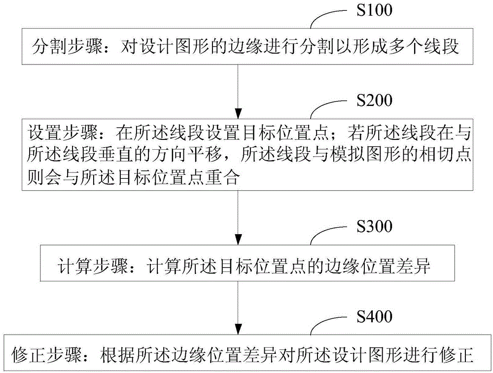
This fixed placement method makes the adaptability to different design graphics insufficient, usually there is a problem of insufficient correction or excessive correction, resulting in low correction accuracy

Method used


Image

  • Optical proximity effect correcting method and system
  • Optical proximity effect correcting method and system
  • Optical proximity effect correcting method and system

Examples


Embodiment Construction

[0027] In order to facilitate the understanding of the present invention, the present invention will be described more fully below with reference to the associated drawings. Preferred embodiments of the invention are shown in the accompanying drawings. However, the present invention can be embodied in many different forms and is not limited to the embodiments described herein. On the contrary, these embodiments are provided to make the understanding of the disclosure of the present invention more thorough and comprehensive.

[0028] Unless otherwise defined, all technical and scientific terms used herein have the same meaning as commonly understood by one of ordinary skill in the technical field of the invention. The terms used herein in the description of the present invention are for the purpose of describing specific embodiments only, and are not intended to limit the present invention. As used herein, the term "and / or" includes any and all combinations of one or more of ...


PUM


Abstract

The invention provides an optical proximity effect correcting method. A setting mode of a target position of a line segment is not fixed, but is changed along with a graph, and generally, the curve endpoint of an analog graph corresponding to the line segment is used as the reference position of the target position. The curve endpoint can be judged by the following method: if the line segment translates in a direction perpendicular to the line segment, a point, which is tangential to the analog graph, of the line segment is the curve endpoint, and at the moment, the curve endpoint coincides with the target position. For the line segment, EPE at the position, which corresponds to the curve endpoint, of the line segment is maximum generally, image correction is performed according to the EPE, correction frequency can be reduced effectively, insufficient correction degree or excessive correction degree is reduced, an analog result is matched with a target value, and the correction efficiency and the correction precision are improved. The invention further provides an optical proximity effect correcting system.

Description

technical field [0001] The invention relates to the technical field of semiconductor manufacturing, in particular to an optical proximity effect correction method and system. Background technique [0002] In the semiconductor manufacturing process, as the lithography size becomes smaller and smaller, a resolution enhancement technique (RET, resolution enhancement technique) is generally adopted. Among them, below the 180nm technology node, an optical proximity correction technology (OPC, optical proximity correction) in the RET technology is adopted as a conventional technical means. In the correction process, two methods are often used, one is called rule-based OPC, and the other is model-based OPC (MBOPC, Model Based OPC); when the MBOPC method is selected, the design graphics will be divided ( Dissection) into multiple relatively short segments (Segment), and then set the target position point (Target point) of each segment, by introducing edge position error (EPE, Edge ...

Claims


Application Information

Patent Timeline
Patent Type & Authority Applications(China)
IPC IPC(8): G03F1/36
CPCG03F1/36G03F7/70441G06F30/39G06F30/398
Inventor 万金垠王谨恒张雷陈洁
Owner CSMC TECH FAB2 CO LTD
Why Eureka
Try Eureka