
Scene-based image self-adaptive nonuniformity correction method

A non-uniform correction and self-adaptive technology, applied in image enhancement, image analysis, image data processing, etc., to achieve good versatility and adaptability, fast calculation speed and good correction effect

Active Publication Date: 2017-03-08
启东中科光电遥感中心
View PDF6 Cites 4 Cited by
  • Summary
  • Abstract
  • Description
  • Claims
  • Application Information

AI Technical Summary

Problems solved by technology

[0005] Based on the existence of the above problems, the present invention proposes a scene-based image adaptive non-uniform correction method, which can adapt to the non-uniform correction of massive images of various complex ground object scenes, and can solve the inconsistency of uniform characteristics of each spectral segment of the image improve the imaging quality and clarity of the image, and lay the foundation for subsequent image analysis and application

Method used


Image

  • Scene-based image self-adaptive nonuniformity correction method
  • Scene-based image self-adaptive nonuniformity correction method
  • Scene-based image self-adaptive nonuniformity correction method

Examples


Embodiment 1

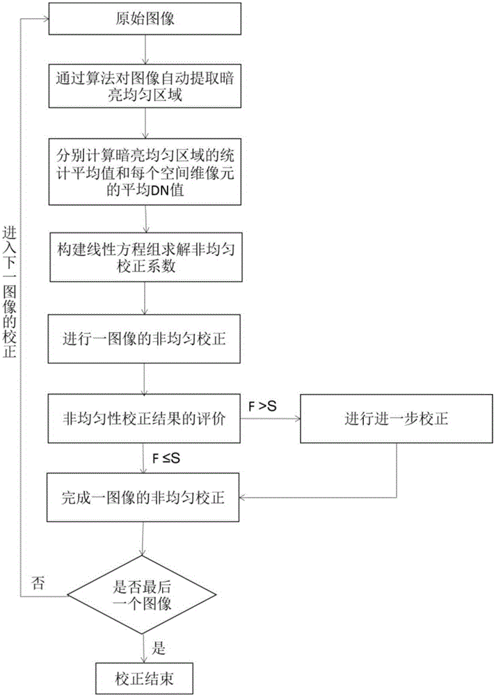
[0029] 1) For an image comprising K pixels, use a computer to automatically sort the Z DN values ​​obtained by each pixel, and intercept a certain range of intermediate values ​​as effective DN values;

[0030] 2) Take the smallest D values ​​among the effective DN values ​​of each pixel to form a relatively dark uniform area (K×D) 1 , the largest L values ​​form a relatively bright and uniform area (K×L) 1 ;

[0031] 3) Calculate the statistical average of the dark uniform area as P 11 , the average DN value of each pixel in the area is Q 11 (i), i=1,2,...,K; Calculate the statistical average value of each bright uniform area as P 21 , the average DN value of each pixel in the area is Q 21 (i), i=1,2,...,K;

[0032] 4) Construct the following linear equation to obtain the gain correction factors a(i), i=1, 2,..., K and offset correction factors b(i), i=1, 2, for each pixel response ..., K:

[0033]

[0034] 5) Perform non-uniform correction on the actual response va...

Embodiment 2

[0042] 1) For an image comprising K pixels, use a computer to automatically sort the Z DN values ​​obtained by each pixel, and intercept a certain range of intermediate values ​​as effective DN values;

[0043] 2) Take the smallest D values ​​among the effective DN values ​​of each pixel to form two relatively dark uniform areas (K×D) 1 , (K×D) 2 The largest L values ​​form a relatively bright and uniform area (K×L) 1 , (K×L) 2 ;

[0044] 3) Calculate the statistical average value of each dark uniform area as P 11 ,P 12 , the average DN value of each pixel in the area is Q 11 (i), i=1,2,..., K, Q 12 (i), i=1,2,...,K; Calculate the statistical average value of each bright uniform area as P 21 ,P 22 , the average DN value of each pixel in the area is Q 21 (i), i=1,2,..., K, Q 22 (i), i=1,2,...,K;

[0045] 4) Construct the following linear equation to obtain the gain correction factors a(i), i=1, 2,..., K and offset correction factors b(i), i=1, 2, for each pixel respo...


PUM


Abstract

The invention discloses a scene-based image self-adaptive nonuniformity correction method, which comprises the steps of automatically ranking DN values of an image according to different pixels, determining at least one relatively dark uniform region and at least one bright uniform region, calculating to obtain a correction coefficient of each pixel according to an algorithm, and completing nonuniformity correction of the image. The scene-based image self-adaptive nonuniformity correction method is suitable for nonuniformity correction of massive images with great correction difficulty and severe nonuniformity of complex scenes, dark objects, infrared image and the like, significantly simplifies the complexity and reduces the cost of correction, is based on scenes but breaks through the limitations of the scenes, has good universality and adaptivity, does not need manual interpretation, is fully automatic in calibration, has fast calculation speed and good correction effect, improves imaging quality of the image, and lays a foundation for subsequent image analysis and application.

Description

technical field [0001] The invention relates to the technical field of optical remote sensing imaging, in particular to a scene-based image self-adaptive non-uniform correction method. Background technique [0002] Infrared focal plane detectors are the core components of existing infrared imaging or detection systems. They are widely used in military and civilian fields. Key technologies for rapid development in the field. With the improvement of the technical level of the focal plane detector, the scale of the infrared focal plane has been expanded to millions of pixels. However, due to the limitations of the existing manufacturing process level and materials, the output range of the infrared focal plane array is not the same, that is, the inconsistency of the response output between each pixel when the infrared focal plane array is input in the same uniform radiation field outside, usually called This kind of inconsistency noise is non-uniform noise, which is manifested...

Claims


Application Information

Patent Timeline
IPC IPC(8): G06T5/00
CPCG06T2207/20004G06T2207/10048G06T5/70
Inventor 刘银年胡彬林郝世菁柴孟阳张静曹开钦孙德新
Owner 启东中科光电遥感中心
Learn More