Method for processing precision part by rotating horizontal jig boring machine for 180 degrees

A technology of coordinate boring machine and precision parts, which is applied in the field of horizontal coordinate boring machine rotating 180° to process precision parts, can solve the problems affecting the machining accuracy of parts, machining error, programming center positioning error, etc., to improve machining accuracy and widely popularize and apply value. Effect

Active Publication Date: 2017-03-15
LUOYANG INST OF ELECTRO OPTICAL EQUIP OF AVIC
View PDF7 Cites 13 Cited by
  • Summary
  • Abstract
  • Description
  • Claims
  • Application Information

AI Technical Summary

Problems solved by technology

[0007] The disadvantages of the traditional processing method are: First, it is difficult or impossible to install the part programming center on the rotation center of the worktable. There is a positioning error between the programming center and the worktable center. After the part is rotated 180°, the characteristic coordinate value of the part to be processed should have The geometric basis of the part remains unchanged, but due to the existence of positioning errors, the difference will be reproduced on the coordinate values ​​after rotation, resulting in machining errors; the second is that the horizontal coordinate boring increases with the number of machining operations, and the difference between the worm gear and worm in the turntable There will be a gap between them. When the turntable rotates within the range of 0° to 180° during programming, the backlash cannot be eliminated. If the backlash is too large or the processed parts are long, the coaxiality of the machine tool may exceed the tolerance range, which will affect the machine tool. Rotation accuracy, which in turn affects the machining accuracy of parts
That is to say, because the positioning error of the part and the rotation accuracy error of the machine tool will affect the machining accuracy of the part

Method used


Image

  • Method for processing precision part by rotating horizontal jig boring machine for 180 degrees
  • Method for processing precision part by rotating horizontal jig boring machine for 180 degrees
  • Method for processing precision part by rotating horizontal jig boring machine for 180 degrees

Examples


Embodiment Construction

[0021] Embodiments of the present invention are described in detail below, and the embodiments are exemplary and intended to explain the present invention, but should not be construed as limiting the present invention.

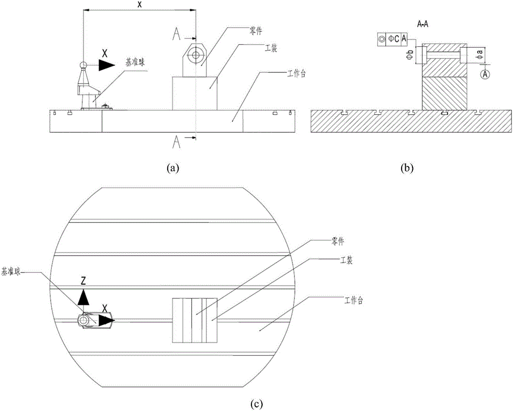
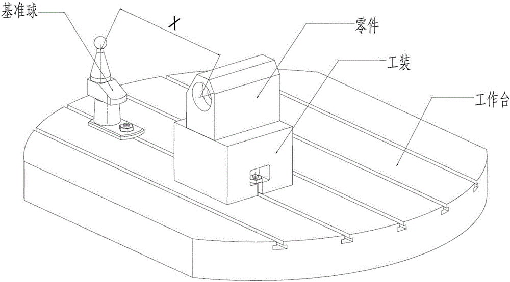
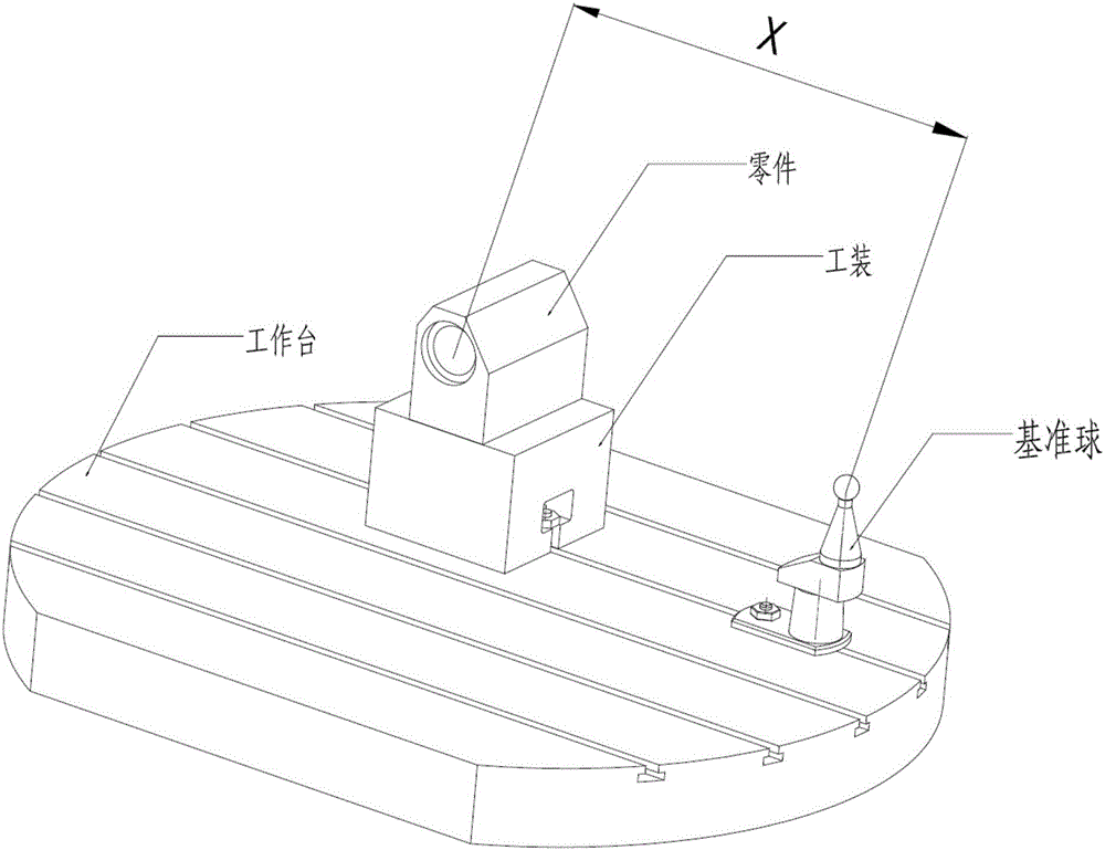
[0022] The invention uses the principle that the distance between the reference ball and the reference of the part remains unchanged before and after the workbench rotates 180° to process the feature of the part. The parts suitable for processing in the present invention should have the following characteristics: ① The worktable needs to be rotated 180° for processing; ② The position accuracy such as coaxiality and position degree needs to be guaranteed to be high.

[0023] During processing, firstly, the table of the horizontal coordinate boring machine is at the 0° position, and the tooling, parts and reference ball are clamped. The reference ball uses a reference ball for high-precision positioning. The X-axis is perpendicular to the plane of the worktable....


PUM


Abstract

The invention provides a method for processing a precision part by rotating a horizontal jig boring machine for 180 degrees. Firstly, when a workbench of the horizontal jig boring machine is in a 0-degree position, a tool, a part and a reference ball are clamped, and metering is performed so as to align the reference axis of the part, so that the reference axis of the part is perpendicular to the X axis of a coordinate system of the workbench; in the position of which the height is the same as the plane of the workbench, an infrared probe is used for measuring central coordinates of the reference ball, reference axis coordinates of the to-be-processed part are measured, the distance between the center of the reference ball and the to-be-processed reference axis is recorded, and the characteristics and reference of the part are processed when the workbench is in the 0-degree position; then the workbench is rotated for 180 degrees, similarly, in the position of which the height is the same as the plane of the workbench, the infrared probe is used for measuring the center of the reference ball, the central coordinates of the reference ball are used as the reference, and the distance X which is recorded previously is matched, so that numerical control programs are compiled, and the to-be-processed characteristics are processed. According to the method, in the conditions that the programming center of the part is not in the axis rotating center of the workbench and rotary errors exist in the rotary center of the workbench of a machine tool, the processing precision can be effectively increased, and wide popularization and application values are obtained.

Description

technical field [0001] The invention relates to the technical field of machining, in particular to a method for machining precision parts by rotating a horizontal jig boring machine by 180°. Background technique [0002] With the increasing use of high-precision machine tools, people usually use machine tool accuracy to ensure the accuracy of parts, but even advanced machine tools require manual debugging, and the machine tool accuracy is not static. The coordinates of the center of rotation of the machine tool will not However, with the wear and aging of the machine tool, the gap between the parts will expand, or after some parts of the machine tool collide, the center of rotation of the machine tool may change. Therefore, the rotary center of the machine tool must be regularly measured and verified to ensure the accuracy of the workpiece machining. [0003] On the other hand, in order to meet the high-precision performance requirements of products, more and more parts hav...

Claims


Application Information

Patent Timeline
Patent Type & Authority Applications(China)
IPC IPC(8): B23B35/00B23B39/04
CPCB23B35/00B23B39/04
Inventor 王德山刘东晓
Owner LUOYANG INST OF ELECTRO OPTICAL EQUIP OF AVIC
Why Eureka
Try Eureka