Clamping plate and method for manufacturing a clamping plate

A technology of pressing plate and structure, which is applied in the direction of manufacturing tools, maintenance and safety accessories, clamping, etc., can solve the problems of mechanical stability of the matrix that damages the pressing plate, weak fixtures, etc., to facilitate the transportation of heat and improve work results , Improve the effect of cooling power

Inactive Publication Date: 2017-03-15
ROHM CO LTD
View PDF2 Cites 2 Cited by
  • Summary
  • Abstract
  • Description
  • Claims
  • Application Information

AI Technical Summary

Problems solved by technology

Furthermore, the use of auxiliary holes leads to a local weakening of the clamp, thereby impairing the mechanical stability of the base body of the pressure plate

Method used


Image

  • Clamping plate and method for manufacturing a clamping plate
  • Clamping plate and method for manufacturing a clamping plate
  • Clamping plate and method for manufacturing a clamping plate

Examples


Embodiment Construction

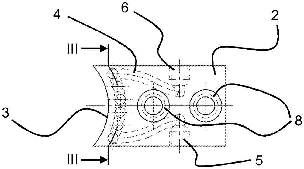
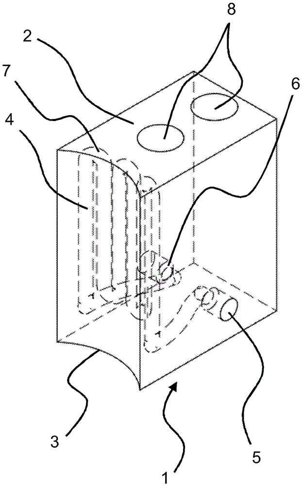
[0030] figure 1 Shown is a pressure plate 1 which is provided for clamping or holding a workpiece. The pressure plate 1 is substantially formed by a base body 2 and has on one side a clamping contour 3 formed in the shape of a circular segment in the exemplary embodiment shown. as in figure 1 As indicated by the dashed lines in the middle, coolant channels 4 are formed in the base body 2 of the pressure plate 1 , which are delimited by a coolant inlet 5 and a coolant outlet 6 . In the exemplary embodiment shown, the coolant channel 4 , which has a plurality of elbow sections 7 , follows the course of the clamping contour 3 in a curved manner. Furthermore, receptacles 8 for receiving fastening means can be seen in the upper side of the base body 2 , with which the pressure plate 1 can be fastened to suitable clamping means.

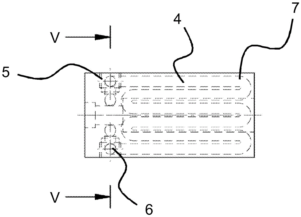
[0031] as in figure 2 As can be seen from the plan view of the pressure plate 1 according to the invention shown in , the shape of the coolant channe...


PUM


Abstract

The invention provides a clamping plate and a method for manufacturing the clamping plate. The clamping plate for clamping or holding a workpiece is described. The clamping plate includes a base body (2) and a clamping contour (3), which is provided for abutment against a workpiece and can be cooled by a cooling device. The cooling device is implemented by at least one coolant duct, which is provided for receiving a coolant and which is formed in the base body by a generative production (e.g., additive manufacturing) process. The formation of the base body is free of auxiliary bores. Furthermore, a method for manufacturing a clamping plate is described.

Description

technical field [0001] The invention relates to a clamping plate for clamping or holding a workpiece, said clamping plate having a base body and a clamping contour, which is provided for abutting against a workpiece and which can be cooled by means of a cooling device. Furthermore, the invention relates to a method for producing a press plate according to the invention. Background technique [0002] Various pressure plates are known from the prior art, which are designed differently depending on the purpose of use. The clamping plate concept here also includes other holding means, such as, for example, grippers or holding claws. However, when using such pressure plates, for example during hard turning, cutting or laser machining of workpieces, there is often the problem that the heat generated during machining of said workpieces is conducted via the pressure plate into the clamping mechanism and finally to the connected parts. In the machine unit, the machine unit is thus ...

Claims


Application Information

Patent Timeline
Patent Type & Authority Applications(China)
IPC IPC(8): B23P15/00B25B29/00
CPCB23P15/00B25B29/00B23Q3/103B23Q11/126B25B1/24B25B1/241B33Y80/00B23Q3/06B25B5/163B33Y10/00
Inventor E.施魏格特J.格雷斯勒
Owner ROHM CO LTD
Why Eureka
Try Eureka