Device and method for automatic grinding and polishing of illumination optical fibers and cables

A fiber optic cable and automatic technology, applied in the field of mechanical processing, can solve problems such as difficult fixation, unstable pressure, and unstable motion trajectory, and achieve the effects of simple processing, improved production efficiency, and avoiding unstable pressure

Inactive Publication Date: 2017-03-15
QINGDAO O MEC MEDICAL TECH
View PDF4 Cites 4 Cited by
  • Summary
  • Abstract
  • Description
  • Claims
  • Application Information

AI Technical Summary

Problems solved by technology

[0002] Lighting fiber optic cables are widely used in urban lighting, medical and other fields. At present, the traditional way to achieve grinding and polishing in the processing of such fiber optic cables is to fix the workpiece on a simple hand-held tooling, expose the polished surface to the outside of the tooling, and grind and polish the shaft. When the grinding and polishing shaft drives the grinding and polishing tool to rotate at a certain speed, it is equipped with corresponding grinding auxiliary materials, such as water, sandpaper, emery, polishing fluid, etc., the operator holds the tooling, and the workpiece to be ground and polished faces The surface of the grinding and polishing tool is rotating and loaded with grinding auxiliary materials. The operator holds the tooling to apply pressure to the workpiece so that the surface of the workpiece to be ground and the su

Method used


Image

  • Device and method for automatic grinding and polishing of illumination optical fibers and cables
  • Device and method for automatic grinding and polishing of illumination optical fibers and cables
  • Device and method for automatic grinding and polishing of illumination optical fibers and cables

Examples


Embodiment 1

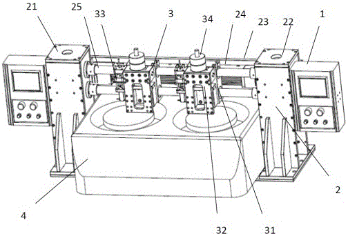
[0019] Example 1: The product to be ground and polished is a medical light guide optical fiber bundle, which is bound together by thousands of optical fibers with a diameter of tens of microns to form a guide beam with a diameter of 5 mm. The end face of the guide beam to be ground and polished is made of optical fiber, glue and Composed of stainless steel, the grinding and polishing machine (4) drives a grinding and polishing tool with a diameter of 200mm. The grinding and polishing auxiliary materials are diamond sandpaper with a specific particle size and grinding liquid. The grain size of the sand paper is 15 μm and 1 μm respectively. Grinding and polishing machine (4) drives a grinding and polishing tool with a diameter of 200 mm and 15 μm diamond sandpaper with pure water at a speed of 100 rpm / min for 2 minutes to grind the end face to be ground until the optical fiber, glue and stainless steel are on the same end face, and the end face is smooth and polished. The machine...


PUM


Abstract

The invention provides a device and method for automatic grinding and polishing of illumination optical fibers and cables to solve the problems. On the basis of the traditional machining process, an automatic device is additionally arranged, movement in the X-axis direction and movement in the Z-axis direction are provided for a workpiece, and workpiece grinding and polishing pressure stabilizing, grinding and polishing walking track path fixing, workpiece grinding and polishing angle fixing and machining time free setting are achieved. In the grinding and polishing process, unnecessary human factors are eliminated to achieve automatic grinding and polishing of the workpiece; compared with the traditional manual machining manner, the device and method have the beneficial effects that the machining process is simplified, the product quality is improved, the machining efficiency is improved, and the production cost is reduced; and the structural design is simple, the process is easy to achieve, and the device and method are suitable for the producing and machining process of part of medical illumination optical cables.

Description

technical field [0001] The invention relates to an automatic grinding and polishing device and method for lighting optical fiber cables, belonging to the field of mechanical processing. Background technique [0002] Lighting fiber optic cables are widely used in urban lighting, medical and other fields. At present, the traditional way to achieve grinding and polishing in the processing of such fiber optic cables is to fix the workpiece on a simple hand-held tooling, expose the polished surface to the outside of the tooling, and grind and polish the shaft. When the grinding and polishing shaft drives the grinding and polishing tool to rotate at a certain speed, it is equipped with corresponding grinding auxiliary materials, such as water, sandpaper, emery, polishing fluid, etc., the operator holds the tooling, and the workpiece to be ground and polished faces The surface of the grinding and polishing tool is rotating and loaded with grinding auxiliary materials. The operator ...

Claims


Application Information

Patent Timeline
IPC IPC(8): B24B37/00B24B37/005B24B37/27B24B37/34
CPCB24B37/00B24B37/005B24B37/27B24B37/34
Inventor 秦义宏樊爱玉
Owner QINGDAO O MEC MEDICAL TECH
Why Eureka
Try Eureka